
 Es
Es  Fr
Fr  Pt
Pt  En
En 

Neu in nanoCAD
Version 26

Call commands through the command line or dynamic input using familiar abbreviations, reduce typing time, and streamline your drafting workflow.
In partial opening mode, only objects that match user-defined criteria (the selected view and layers) are loaded, significantly reducing system resource consumption and speeding up file opening. Other objects remain in the file on disk and are not loaded into RAM. Unloaded objects are not displayed and cannot be directly edited, but their associative links are preserved.
To partially open a file, click the arrow next to the Open button in the standard Open File (OPEN) dialog box and select Open Partially:


Freezing is controlled through the External References panel. To assign a status to a loaded reference, select Freeze from the context menu.

Freezing an external reference frees up RAM. When frozen, the external reference itself is not loaded into memory, and the graphics cache obtained at the time of freezing is used for display.

A new Shadows property has been added to the 3D Visualization section of the Properties panel.

A SUNPROPERTIES command has been developed for creating realistic natural lighting that simulates sunlight. This command opens the Sun Management dialog, where you can fine-tune sunlight parameters based on the object's geographic location, specific date, and time of day. Sunlight parameters can be saved as presets. Saved presets are displayed in a table on the left side of the dialog.

- Yes – the document will be loaded.
- No – the document will not be loaded.
- Do not show this message again – disables the warning message.
The message is also displayed in the command line.

The

Polar angle measurement options have been added to the Polar Tracking tab of the Drawing Settings dialog box:

Absolute – enables the angle measurement mode based on the X-axis of the WCS.
Relative to Last Segment – enables the angle measurement mode based on the direction of the previous line.
Snapping to the boundary points of text objects is now supported when Track to Alignment Point is enabled in the Polar Tracking tab of the Drafting Settings (DSETTINGS) dialog.

Construction geometry has been updated for the Parallel snap. Along with the parallel rubber band, a rubber band perpendicular to the object is displayed on the screen, allowing you to draw a linear object normal to an existing object.

Unlike the standard Perpendicular snap, the second point can be specified anywhere during construction, not necessarily on the object to which the normal is being drawn.
Object snap capabilities have been expanded for Mesh, Polyface Mesh, and 3D Face objects:
- When 3D object snaps are enabled (Face Nearest, Vertex, Face Center, Face Perpendicular), snapping to the mesh face is triggered.
- When 3D object snaps are disabled but the Object Snap (OSNAP) mode is enabled (Nearest, Node, Center), snapping to the face edge is triggered.

Display coordinate tooltips – subsection for controlling the display of tooltips for coordinates (DYNPIVIS system variable):
- After starting to enter coordinate values – display tooltips only when you start entering coordinate values.
- When the command requests a point input – display tooltips when a command prompts for a point.
- Always – always display tooltips, even in non-command mode.
Tooltip Size – specifies the size of the tooltips. The range is from -3 to 6. The default is 0.
To display the Z coordinate in tooltips next to the cursor, enable the Always show Z.
New command line color settings have been added to the Options (OPTIОNS) dialog.

- Default – command line colors are specified by the visual style of the interface.
- Custom – specify custom colors:
- Command Line Background Color – set the background color.
- Command Line Text Color – set the command line text color.
New settings have been added to the "Don’t Show Again" Messageboxes section of the Options (OPTIONS) dialog.

Update relative paths of external references – Enable/Disable the message when changing the file location using the Save As command for drawings containing external references with relative paths.
Warning about embedded raster – Enable/Disable the warning when embedding a raster into a drawing.
Warning if the UCS file is not found – Enable/Disable the warning about missing user coordinate system file.
Added the ability to disable the Generation of a Problem Report (REPORTPROBLEM) in the Feedback section of the Options (OPTIONS) dialog.

A Max Raster Size setting has been added to the Default Raster Properties section of the OPTIONS dialog (MAXRASTERSIZE system variable). This setting specifies the maximum size of raster (in MB) that can be fully loaded into RAM. If the size is larger than this value, inline dynamic loading will be used, and raster will be loaded in read-only mode.


When you call this command, the Extended Properties functional bar appears:

To construct a quadrangle, specify the following properties:
- Type of quadrangle – rectangle, parallelogram, or rhombus.
- Construction method.
- Coordinates and/or dimensions of the quadrangle. The coordinates and dimensions of the quadrangle can be specified on the screen with the mouse cursor or entered as values in the corresponding fields.
This command allows you to construct various types of polygons:
 Circumscribed – constructs a circumscribed polygon by specifying the radius of the circle containing the midpoints of the polygon's sides.
  Inscribe Circumscribed d – constructs an inscribed polygon by specifying the radius of the circle containing the polygon's vertices.
  Star – constructs a polygon with alternating external and internal vertices.
When you call this command, the Extended Properties functional bar appears:

To create a polygon, specify the following properties:
- Number of vertices (rays).
- Polygon Type: circumscribed polygon, inscribed polygon, star.
- Coordinates of the center point.
- Polygon dimensions.
Polygon properties can also be specified via the command line.

The Batch Processing utility (BATCHPROCESS) now has an additional option: Close the dialog after checking (enabled by default).

This option enables/disables automatic closing of the Batch Processing dialog box after file validation:
- Report save folder — the path to the folder where the program will save the batch file processing report. The default folder is C:\Users\UserName\AppData\Local\Temp.
- Report name — the field for specifying the name of the batch file processing report. A timestamp of the form HH-MM-SS_DD.MM.YYYY is automatically appended to the name.

Layers grouping is useful if a document contains a large number of layers or if you frequently need to change the settings for several layers (for example, to quickly turn them on/off or to enable/disable printing capability).
A filter generates a list of layers that meet the filter criteria. Filter selection is performed in the Layer Filter Properties dialog box.

Layer configurations are saved sets of layer settings that allow you to quickly switch between different layer states in a drawing, such as visibility, freezing, locking, etc. A configuration is created for all layers in the document.
Detailed work with layer configurations is performed in the Layer States Manager dialog box.

- horizontally,
- vertically,
- at an angle.
New Text Mask (TEXTMASK) and Text Unmask (TEXTUNMASK) commands have been added for applying/removing masking behind text. A Wipeout and Solid object can be used as a mask.

A new Reset MText Formatting (REMOVEMTEXTFORMAT) command has been added for resetting manual multiline text formatting. This removes manual formatting, returning it back to the values of
the applied text style.
A new Auto Numbering of Text (TCOUNT) command has been added for sequential numbering of single-line (TEXT) and multiline (MTEXT) text objects, as well as attribute definitions (ATTDEF). Numbering can be displayed as a prefix or suffix, and can also replace specified text.
The ability to create different types of fractions in multiline text (MTEXT) using the characters / (slash), # (hash), and ^ (caret) has been added.
Added tooltips indicating the height and width of multiline text (MTEXT) to the button for setting the width (height) of a text input area:

A new
- Drawing – converts all drawing fields to text.
- Layout – converts all layout fields to text.
- Sheetset – converts all fields in a sheet set to text.
The
Added the ability to edit (MTEDIT) text objects (single-line and multi-line texts, texts in multileaders, texts in DWG tables, attribute values, dimension texts, including those with subdimension text) in block references and external links without having to open them in the corresponding editors.

The Options (OPTIONS) and the Profiles (PROFILES) dialogs have been updated. The visual component has been improved, and the ergonomics of dialog boxes has been optimized.

The Text Decoder (TEXTDECODER) dialog has been updated. The arrangement of controls in the dialog box has been optimized.

The PURGE dialog has been updated. The visual component has been improved, and the ergonomics of the dialog box has been optimized.

The CAD standards checking dialogs have been updated, including Configure Standards (STANDARDS), Check Standards (CHECKSTANDARDS), and Standards Check Options (STANDARDSSETTINGS).
The Viewports (VPORTS), Load/Unload Applications (APPLOAD), Attach Digital Signatures (DIGITALSIGN), and Layout Manager (LAYOUTSMANAGER) dialogs have been updated.
The settings dialogs for the built-in raster printer (PLOT) have been updated.
The Hatch Pattern dialog has been updated. This dialog can be accessed through the Quick Properties (QUICKPROPERTIES) panel.

The Video Subsystem Performance Test (VPERFTEST) dialog has been updated. The visual presentation of information has been improved.

The visual representation of information and warning messages has been optimized.
The appearance of the application window status bar has been changed:
![]()
![]()
![]()
violation.
The
Highlighting of selected areas has been added when Calculating the Object Area (AREA) in the Add Area and Subtract Area modes.
Toolbars (widgets) with base commands have been added in a drawing’s graphic area for the Edit Block Definition (BEDIT), Edit 3D Block Definition (3DBEDIT) and Edit Reference (REFEDIT) commands:
![]()
![]()
The ability to edit dynamic block properties has been added to the Properties panel.

The organization of sheets in sheet sets has been changed. The sheets in a set are now displayed in the same order as the sheet tabs in the original drawing file.
The conversion of absolute paths has been added when editing fields linked to a sheet set.
Added saving of sheet location paths in a documentation set when creating a new documentation set using a template.
Sheet paths in a sheet set are now saved when creating a new sheet set by template.
The ability to shift selected objects in orthogonal increments using the CTRL + arrow keys (Left, Right, Up, Down) has been added. The distance and direction of the shift depend on the snap settings.
The
The
The


A

Added the ability to change properties for the MPolygon object in the Properties panel:
- Fill (hatch) color swatch
- Hatch (pattern) type
- Hatch (pattern) name
- Angle
- Scale
- Spacing
- Cross
Hatch (HATCH) annotation properties have been added to the Properties panel:

Added the ability to change the order of paper formats in the Papers section of the Options (OPTIОNS) dialog box using the Up and Down buttons.

The new XRef selection option has been added for such commands as Layer Off (LAYOFF), Freeze Layer (LAYFRZ), and Freeze Layer in All Viewports Except Current (LAYVPI). This option is used to select the nesting level of external references:
- XRef – If the selected object is contained within an external reference, the external reference layer is turned off/frozen.
- Entity – If the selected object is contained within an external reference, the layer containing the object within the external reference is turned off/frozen.
- None – If an external reference is selected, the layer containing the external reference is turned off/frozen; layers of nested objects are not turned off/frozen.

A warning message has been added to automatically update modified external references (XREF) when opening the Reference Editor (REFEDIT).
You can now copy a selected layout (COPYLAYOUT) by dragging it within the layout tabs area with the left mouse button and holding down the CTRL key.
A request has been added to the silent version of the Purge Document (–PURGE) command to create a text file containing full information about the command's execution:
Save log of purged items? [Yes/No]:
If you select Yes, a txt-file will be created. If you select No, the file will not be created. The default folder is C:\Users\UserName\AppData\Local\Temp.
An Options button has been added that opens the DXF Save As Options dialog box when saving (SAVEAS) and exporting (EXPORT) documents in DXF files. You can now set the DXF file format (ASCII or Binary) and specify a precision value for the ASCII file type.

PDF underlays (UATTACH) now display PDF file markup (text comments, annotations, highlights, and vector graphics that have been added to the PDF file over the main content). Markup is visible in underlay insertion dialogs, on-screen, and in print, but is not imported or available for snapping.
From now on, you can import (IMPORT) PDF files by dragging them from the Explorer into a nanoCAD interface. When dragging a file in a drawing workspace, the PDF data will be inserted as nanoCAD native objects (PDFIMPORT).
It is now possible to create a viewport by the Region (REGION) object using the Viewport by Object (ADDOBJECTVIEWPORT) command.
Flexible viewport locking and unlocking capabilities have been added. The menu is accessible by left-clicking the

- Lock/Unlock Selected Viewports (LOCKUNLOCKSELECTEDVIEWPORTS) – the selected viewports will be locked/unlocked.
- Lock/Unlock All Viewports on the Current Layout (LOCKUNLOCKALLSPACEVIEWPORTS) – all viewports in the current layout will be locked/unlocked.
- Lock/Unlock All Viewports on All Layouts (LOCKUNLOCKALLDOCUMENTVIEWPORTS) – all viewports in all layouts will be locked/unlocked. This command is also available in Model space.
Group movement of block attributes (ATT) in model space is now possible. To do this, hold down the SHIFT key and sequentially select multiple attributes with the left mouse button.
When opening a document, an additional check for the presence of authoring elements that are not part of dynamic blocks is now performed. If such elements are detected, a warning message is displayed prompting you to delete the found elements.
- Yes – Delete authoring elements that are not part of dynamic blocks from the file (CLEARAUTHORINGELEMENT command). After deleting elements, the file must be saved before closing.
- No – Do not delete authoring elements in the file being opened.

- Yes – Delete empty entries in the sort table from the file (–PURGE command, sorTTable option). The command line displays the number of entries successfully deleted. After deleting, the file must be saved before closing.
- No – Discard the deletion of empty entries in the sort table in the file being opened.
When changing the file location using the Save As command for drawings containing external references with relative paths, the following message has been added:

- Yes – the document is saved with updated relative paths for external references. When opening such a file, the external references status in the External References functional bar will be Loaded.
- No – the external reference paths are not changed. When opening such a file, a warning message will appear: References – Files not found. The external references status in the External References functional bar will be File not found.
- Do not show this message again – disables the warning message. You can enable the display of the warning message in the "Don’t Show Again" Messageboxes section of the Options dialog (OPTIONS).
The new MAXNUMPATTS system variable defines the maximum number of linetype samples (LINETYPE) in an object. Valid values range from 0 to 1,000,000. The default value is MAXNUMPATTS = 10,000. If the specified value is exceeded, the line is displayed as a solid line. When the variable is set to 0, the limitation is removed, and lines are drawn according to the sample, regardless of the number of samples. However, removing the limit may reduce performance in busy drawings with long lines.
The new VISIBLESCENEDEPTH system variable specifies the method for determining the depth occupied by objects in the visible part of the scene. Valid values:
- 0 – Total scene depth, without calculating the boundaries of visible objects (default).
- 1 – Fast calculation, but with less accuracy, by transforming the total boundary of visible block objects into the local coordinate system.
- 2 – Accurate but slow calculation by summing the boundaries of visible block objects transformed into the local coordinate system.
The REVCLOUDGRIPS system variable has been added. It determines the number of grips for a cloud (REVCLOUD) object:
- 0 – Grips are displayed for each cloud arc segment.

- 1 – Grips are displayed at significant points of the original cloud object (polyline).

For editing dimensions using grips, the Continue Dimension and Baseline Dimension options have been added to the dynamic menu that appears when hovering crosshair over an arrow editing grip:

- Continue Dimension – creates a sequence of dimensions, where each subsequent dimension starts from the end point of the previous one. The Continue Dimension (DIMCONTINUE) command options are available in the command line.
- Baseline Dimension – creates a sequence of base dimensions, where each subsequent dimension is measured from a common starting point. The Baseline Dimension (DIMBASELINE) command options are available in the command line.
From now on, you can move, delete and/or replace individual array elements using the Edit Array (ARRAYEDIT) command.
When generating a Problem Report (REPORTPROBLEM), the option to include the licensing system log (nanoLM.log) has been added.

The ability to create sets of package parameters has been added to the file package generation command (ETRANSMIT):

You can now select a file to open in the start window (WELCOMESCREEN) before the application loads.
Critical Errors
Fixed a bug that caused the program to crash on user files when editing text (MTEXT) with fields (FIELD).Fixed a bug that caused the program to freeze when printing (PLOT) user files, including files with hatches.
Fixed a bug that caused the program to crash when working with custom drawings containing variation elements.
Fixed a bug that caused the program to crash on user files when working with a spline (SPLINE) with the Midpoint object snap mode enabled.
Fixed a bug that caused the program to freeze on user files with 3D polylines (3DPOLY) when hovering the cursor over object snap points (with the Centroid and Apparent Intersection modes enabled simultaneously).
Fixed a crash when opening drawings with a large number of proxy objects without a graphical representation.
Fixed a bug that caused the program to freeze when hatching an object (HATCH) using the Add: Pick Points method.
Fixed a bug that caused the program to freeze when executing the Save as Raster (RASTEROUT) command with a high DPI.
Fixed a crash when moving an object to a frozen or disabled layer using the Quick Properties (QUICKPROPERTIES) functional bar.
Fixed a bug that caused the program to freeze when snapping to a Big Radius (DIMJOGGED) dimension located inside a block (BLOCK).
Other Fixes
Fixed errors when opening custom drawings created in other CAD systems.Fixed issues with restoring drawings containing variation elements and empty entries in sorting tables, as well as files saved in earlier versions of the program.
Fixed a bug that prevented the Synchronize Attributes (ATTSYNC) command from updating the order of block entry attributes in the Properties panel and in the Edit Block Attributes (ATTEDIT) and Enhanced Attributes Editor (EATTEDIT) dialogs.
Fixed a bug that caused polyline (PLINE) editing grips to display incorrectly in a locked viewport (VIEWPORT).
Fixed errors when exporting splines (SPLINE) from other CAD systems.
Fixed the program freezing when selecting multiple layers in the Layers (LAYER) dialog box.
Fixed a bug when switching user coordinate systems (UCS) did not work in a file saved using WBLOCK.
The default folder for the Write Block to a Separate File (WBLOCK) command has been changed to the Documents folder.
Fixed a bug where the return to world coordinate system (CLEARUCS) command did not work.
Fixed an error that occurred when trimming (TRIM) a straight spline created in ORTHO mode.
Fixed a bug due to which, when stretching (STRETCH) a leader (LEADER), the leader shelf moved out of alignment with the text.
Fixed a text flipping error when mirroring (MIRROR) a multileader (MLEADER) in a rotated UCS.
Fixed a bug where multileader (MLEADER) rotation results were not displayed correctly when changing the current angle by more than 90 degrees.
Fixed a bug that caused STRETCH results for MLEADER to be displayed incorrectly.
Fixed a bug where it was impossible to interact with text (MTEXT) outside the text area boundaries.
Fixed an issue where the text would flicker in the edit field of multiline (MTEXT) or single-line (TEXT) text if the drawing contained constraints.
Fixed a bug where text formatting settings were not applied after pasting multiline text (MTEXT) via the clipboard.
Fixed a bug where multiline text did not inherit layer properties when converting text to mtext (TEXT2MTEXT).
Fixed an error in specifying line spacing values in the Paragraph (Fixed an error that occurred when trimming (TRIM) a straight spline created in ORTHO mode.
Automatic rebalancing of the point cloud between disk and memory.
Added system variables NPCWHOLEMEMORY and NPCMAXMEMORY to control the size of the portion of the cloud loaded into RAM.
Optimized point cloud storage by excluding the current color channel from the NPC file.
Improved the design of the Point Cloud Information (NPC_INFO) dialog.

Improved the design of the histograms of classes and reflection numbers for the Point Cloud Information (NPC_INFO) dialog.

Improved the design of the Intensity histogram for the Point Cloud Information (NPC_INFO) dialog.

Improved the design of the View Mode functional bar when coloring the point cloud by Elevation, Intensity, Deviations, and Fractal Dimension.

Added explanatory tooltips to the buttons in the View Mode functional bar.
Improved implementation of coloring by Deviation and Fractal Dimension.
Improved the design of the Point Cloud Import (NPC_IMPORT) dialog.
Automatic enabling snap to Node for NPC_CLIP_SPHERE, NPC_CLIP_SPHERE_INV commands.
Improved functionality of the Project Manager panel (NPC_PROJECT_MANAGER). A scroll bar has been added.
Unfound clouds are now displayed in gray in the Properties panel.
When exporting to LAS using the NPC_EXPORT command, a warning about data loss was added for classes with codes higher than 31.
Histogram colors have been changed.
The NPC_SECT_ command has been added, allowing dynamic adjustment of the section depth and movement step in an existing section without re-creating it.
The NPC_VIEWMODE interface for creating and editing attribute crops has been added to the visualization panel.
Incorrect positioning of numbers indicating the boundaries of the selected interval on the elevation gradient scale has been fixed in the NPC_VIEWMODE command.
The following changes have been made to the Misc section for point clouds:
- The Frozen status has been moved from the modes to a separate setting with a checkbox.
- The Transformation status has been converted to a Transformation locked checkbox for more intuitive operation.
Point Cloud Import
Fixed a preview window error when importing point clouds with different numerical orders.Fixed an error where metachannel checkboxes remained enabled even when there was no data in these channels. Empty channels are now automatically disabled and marked with a warning icon during import.
Version 25

Das Design des Dialogfelds Dateipaket erstellen (ETRANSMIT) wurde aktualisiert und dessen Funktionsweise optimiert. Die Dateitypsymbole wurden geändert und es wurde die Möglichkeit hinzugefügt, mehrere Dateien mit den Tasten UMSCHALT und STRG auszuwählen.

Es wurde die Möglichkeit hinzugefügt, die Genauigkeit des Exports (EXPORT) in das STL-Format (*.stl) festzulegen, indem der maximal zulässige Abstand zwischen benachbarten Punkten (Max. Sehnenlänge) angegeben wird.

Für eine bequemere Interaktion mit der Benutzeroberfläche wurden die Symbole ungenutzter Dateien in der Funktionssymbolleiste Externe Referenzen (EXTERNALREFERENCES) geändert.
Ein neuer Befehl Bemaßung mit Abhängigkeiten (DCAUTO) wurde hinzugefügt, um parametrische Bemaßungen mit einem einzigen Befehl einzufügen (ähnlich wie MDIM). Dieser Befehl funktioniert nur im Skizzenbearbeitungsmodus.
Die Symbolleiste Karte über Kontrollpunkte einfügen wurde zum Einfügen einer Rasterkartenunterlage über Kontrollpunkte implementiert. Sie können die Symbolleiste öffnen, indem Sie das Dialogfeld Kartenunterlage (MAPVIEW) öffnen: Wählen Sie auf der Registerkarte Rasterkarten die erforderlichen Parameter aus, aktivieren Sie das Kontrollkästchen Über Kontrollpunkte unten im Dialogfeld und klicken Sie auf die Schaltfläche OK.

Für den Export von GLB- und GLTF-Dateien wurde die Möglichkeit hinzugefügt, die Drehung um die Y-Achse (nach oben) festzulegen:


Wenn Sie auf die

- Linie
- Polylinie
- Bogen
- Kreis
Die automatische Korrektur ermöglicht Ihnen Folgendes:
- Objekte zu löschen, die kleiner als die angegebene Größe sind
- Kontakte zwischen Objekten wiederherzustellen
- Fragmente in ein einzelnes Objekt „einzufügen”
- Linien entlang Standardrichtungen (UCS, Ortho-Raster) auszurichten, sofern ihre Abweichungen den vom Benutzer angegebenen Wert nicht überschreiten
- die Reihenfolge der Rundung der Koordinaten von Zeichnungsobjekten zu ändern

Der Befehl erstellt einen Ordner mit Angabe des Zeitpunkts und bildet darin ein Dateipaket für die Übertragung. Anschließend wird der Benutzer im Dialogfeld aufgefordert, Dateien zum Senden hinzuzufügen oder zu entfernen. Es stehen Ihnen zwei Optionen zur Verfügung: Sie können den Bericht als ZIP-Archiv speichern und auf Ihrem Computer ablegen (Schaltfläche „Bericht speichern“) oder ihn per E-Mail im EML-Format versenden (Schaltfläche „Bericht senden“).

Die Einstellung Aktuelle Datei automatisch hinzufügen wurde zur Liste der ausgewählten Dateien für die Stapelverarbeitung hinzugefügt:

Standardmäßig ist diese Einstellung aktiviert, und wenn Sie den Befehl Stapeldateiverarbeitung (BATCHPROCESS) ausführen, wird die aktuelle Zeichnung automatisch zur Liste Ausgewählte Dateien hinzugefügt.
Sie können nun nicht nur Dateien mit der Erweiterung DWG (Zeichnungsformat), sondern auch DWT (Vorlagenformat) zur Liste Ausgewählte Dateien hinzufügen.

Die Assoziativität von DST-Formatdateien wurde hinzugefügt. Nun werden Dokumentationssatzdateien automatisch in nanoCAD geöffnet und gleichzeitig die Symbolleiste Blattsatz-Manager (SHEETSET) gestartet.
Die Möglichkeit, Blätter innerhalb des Dokumentensatzes/der Dokumentengruppe durch einfaches Ziehen zu verschieben, wurde in der Symbolleiste Blattsatz-Manager (SHEETSET) hinzugefügt.
Die Benutzerfreundlichkeit des Dialogfelds Blattsatz umbenennen und umnummerieren in der Symbolleiste Blattsatz-Manager (SHEETSET) wurde durch die automatische Auswahl des Felds Nummer verbessert.
Auf der Registerkarte Blattlisten der Symbolleiste Blattsatz-Manager wurde die Menüschaltfläche
- Als PDF veröffentlichen
- Auf Plotter veröffentlichen
- Als DWF veröffentlichen
- Als DWFx veröffentlichen
Das Veröffentlichen eines Dokumentensatzes/einer Blattgruppe/eines Blattsatzes/eines Blattes ist auch im Kontextmenü des Baums Blattsatz verfügbar.
Der standardmäßig vorgeschlagene Dateiname für ein mehrseitiges Dokument beim Plotten entspricht nun dem Namen des Dokumentationssatzes und nicht mehr dem Namen des ersten Blattes.

Die Option Hyperlinks einschließen wurde den Einstellungsdialogfeldern für Interner DWFx-Plotter, Interner DWF-Plotter, Interner PDF-Plotter und Drucken als PDF hinzugefügt. Diese Option konvertiert Dokumenthyperlinks in Hyperlinks in einer PDF-Datei.
Für alle internen Drucker wurde die Möglichkeit hinzugefügt, die Einstellungen des Plotgeräts als separate Datei mit der Erweiterung PC3 zu speichern, um die Verwendung auf mehreren Computern zu vereinfachen.
Die Option Unterordner verwenden wurde den Einstellungsdialogfeldern für alle internen Drucker hinzugefügt, um ein zusätzliches Verzeichnis mit dem Formatnamen (DWFx, DWF, EMF, PDF oder Raster) zu erstellen und Dateien im erstellten Unterordner zu speichern. Die Option ist verfügbar, wenn die Modi Vordefinierten Dateinamen verwenden und Dokumentdateiordner verwenden aktiviert sind.
Die PC3-Plotter-Einstellungsdatei kann nun nicht nur im Standardordner für Plotkonfigurationsdateien C:\Users\User_name\AppData\Roaming\Nanosoft AS\nanoCAD x64 25\PlotConfigs, sondern auch in dem Verzeichnis gespeichert werden, in dem sich die DWG-Datei selbst befindet.
Die Suche nach Netzwerkplottern wurde optimiert. Die Zeit zum Herstellen einer Verbindung zu getrennten oder „nicht vorhandenen” Netzwerkplottern wurde auf einige Sekunden reduziert.
Ein neuer Befehl PARAMETERSCURLAYOUT öffnet das Dialogfeld Seite einrichten zum Festlegen der Plot-Einstellungen für das ausgewählte Blatt.
Die Möglichkeit, Tabellen (TABLE) aus XLSX-Dateien ohne vorinstallierte Office-Suite zu laden, wurde implementiert.
In nanoCAD-Tabellen (TABLE) wurden der vollständigen Editor-Oberfläche die folgenden Schaltflächen zum Formatieren von Text in Zellen hinzugefügt: Unterstreichen, Durchstreichen, Überstreichen. Damit können Sie den Wortlaut in mehreren Tabellenzellen gleichzeitig bearbeiten.

- MTEXTFIXED = 0 (oder 1) – Der Text wird entsprechend der Größe und Drehung in der Zeichnung angezeigt.
- MTEXTFIXED = 2 (Standardwert) – Der Text wird in einer geeigneten Größe und in horizontaler Ausrichtung angezeigt.


Die folgenden Kombinationen stehen nun für die Eingabe von hoch- und tiefgestellten Zeichen in mehrzeiligem Text (MTEXT) zur Verfügung:
- hochgestellt – STRG + PFEIL NACH OBEN;
- tiefgestellt – STRG + PFEIL NACH UNTEN.
Die folgenden Kombinationen stehen nun für die Formatierung von Einzeiligem Text (TEXT) zur Verfügung:
- durchgestrichener Text – %%K oder STRG + K;
- unterstrichener Text – %%U oder STRG + U;
- überstrichener Text – %%O oder STRG + O.
Für alle Tools zum Erstellen und Bearbeiten von Mehrzeiligem Text (MTEXT) und Einzeiligem Text (TEXT) wurden die Reihenfolge und die Namen der Absatzausrichtungen vereinheitlicht: Linksbündig, Zentriert, Rechtsbündig, Blocksatz, Verteilt.
Die Funktionalität des Dialogfelds Absatz, das über die Leiste Textformat (MTEXT) aufgerufen wird, wurde erweitert.

Die folgenden Einstellungen wurden hinzugefügt:
- Auswahl des Registerkartentyps sowie Anzahl und Position der Registerkarten, • Einrückungsoptionen und -werte
- Absatzausrichtung
Die Einstellungen für die Abstände vor und nach einem Absatz sowie für den Zeilenabstand innerhalb eines Absatzes wurden erweitert.
Beim Eingeben ungültiger Werte für den Überlappungskoeffizienten im Dialogfeld Hintergrund ausblenden (BACKGROUNDMASK) wird nun eine Warnmeldung angezeigt.

Die Liste der Vorlagen, die im Menü zur Auswahl stehen, ist begrenzt. Um eine andere Vorlage auszuwählen, die nicht in der Liste aufgeführt ist, öffnen Sie das Dialogfeld Vorlage auswählen oder konfigurieren Sie die Liste Vorlagennamen im Abschnitt Vorlagenverwendung des Dialogfelds Optionen (OPTIONS).
Befehl

Sie können eine Vorlage hinzufügen oder entfernen, indem Sie den entsprechenden Befehl im Kontextmenü auswählen. Die Reihenfolge der Vorlagen kann durch einfaches Ziehen und Ablegen geändert werden.


Das Kontextmenü zum Erstellen einer Gruppe (GROUP) wurde optimiert. Die Befehle Gruppe auflösen, Zur Gruppe hinzufügen und Aus der Gruppe entfernen im Kontextmenü sind gesperrt, wenn vorhandene Gruppen und einzelne Objekte vorab ausgewählt sind.
Im Dialogfeld Objektgruppierung (GROUPCMD) wurde der Mechanismus zum Hervorheben von Objekten in der ausgewählten Gruppe auf dem Bildschirm geändert. Das Dialogfeld Objektgruppierung wird nun nicht mehr geschlossen. Wenn die Option Hervorheben aktiviert ist, wird die Gruppe, deren Zeile in der Dialogliste ausgewählt ist, auf dem Bildschirm hervorgehoben.


Die Funktion Farbe auswählen (COLOR) wurde aktualisiert. Die Funktion zum Speichern der Position des Dialogfelds auf dem Bildschirm wurde konfiguriert. Es wurden Optionen zum Festlegen einer Farbe anhand eines beliebigen Punkts auf dem Bildschirm (mit einer Pipette) und im HSV-Farbmodell hinzugefügt. Die Möglichkeit, die Farbnummer auf der Registerkarte Echtfarben mit den Pfeiltasten der Tastatur zu ändern, wurde implementiert.

Das Dialogfeld Hyperlink (HYPERLINK) wurde überarbeitet.

Das Dialogfeld Benutzerdefinierten Pfeilblock auswählen wurde aktualisiert.

Das Dialogfeld Punktstil wurde aktualisiert.

Es wurde eine neue Systemvariable OFFSETGAPTYPE hinzugefügt, die den Typ der Außenecken beim Konstruieren eines Polylinienversatzes (OFFSET) festlegt:
- OFFSETGAPTYPE = 0 (Standardwert) – die Versatzlinien werden zu einer Ecke verlängert;
- OFFSETGAPTYPE = 1 – an den Schnittpunkten der Versatzlinien wird eine Verrundung mit einem Radius konstruiert, der dem Versatzabstand entspricht;
- OFFSETGAPTYPE = 2 – an den Schnittpunkten der Versatzlinien wird eine Fase konstruiert, der senkrechte Abstand jeder Fase zum entsprechenden Scheitelpunkt des Originalobjekts entspricht dem Versatzabstand.

Der Fang Schnittpunkt für Spline-Selbstschnittpunkte wurde hinzugefügt (SPLINE).
In der Symbolleiste Externe Referenzen (EXTERNALREFERENCES) wurden für eine komfortablere Interaktion mit der Benutzeroberfläche die folgenden Symbole für den Status externer Referenzen hinzugefügt: Datei nicht gefunden, Nicht geladen, Nicht referenziert.

Die Möglichkeit, die Transparenz (TRANSPARENCY) des Hintergrunds von Rasterbildern im TIF-Format (TIFF) zu ändern, wurde hinzugefügt.
Der neue Befehl
Die Informationshinweise wurden für Schaltflächen im Dialogfeld Dateipaket erstellen (ETRANSMIT) und für Layer-Parameter-Symbole in der Symbolleiste Layer (LAYERSQUICK) hinzugefügt.
Die Möglichkeit, alle Eigenschaftsgruppen gleichzeitig zu öffnen/auszublenden, wurde in der Symbolleiste Eigenschaften (INSPECTOR) hinzugefügt. Klicken Sie dazu auf die Schaltfläche
Die Methode zum Bearbeiten von Bemaßungen durch Doppelklicken wurde geändert. Wenn nun die Option Bemaßung deaktiviert ist (im Dialogfeld Einstellungen nanoCAD (PARAMS), Registerkarte Hauptoptionen, Abschnitt Bearbeiten – durch Doppelklick), wird der Befehl zum Bearbeiten von mehrzeiligem Text (MTEDIT) aufgerufen.

Die Formulierungen der Warnmeldungen zu einer großen Anzahl externer Referenzen (XREF) wurden korrigiert.
Die Beschreibungen der Unterabschnitte im Abschnitt Systemeinstellungen des Dialogfelds Optionen (OPTIONS) erläutern, wann Änderungen wirksam werden.
Der Befehl Layout speichern als… (LAYOUTTOTEMPLATE) wurde zum Kontextmenü der Registerkarten Modell und Layout hinzugefügt.
Das Ändern des Modus Mehrere Linien wurde beim Bearbeiten eines mehrzeiligen Attributs im Blockattribut-Manager (BATTMAN) blockiert.
Der Meldungsfeld-Abschnitt Nicht mehr anzeigen wurde im Dialogfeld Optionen (OPTIONS) hinzugefügt, in dem Sie die Anzeige einiger Warnungen verwalten können.

Die visuelle Darstellung von Informationen, Warnungen und Fehlermeldungen wurde optimiert.
Das Programmverhalten bei der Zuweisung von Farbe und Abdeckung (COVERINGBROWSER) wurde optimiert. Sie können nun Farbe oder Abdeckung nur dem gesamten Volumenkörper oder seiner Fläche zuweisen, nicht jedoch einem Scheitelpunkt oder einer Kante. Zu diesem Fall wird eine Warnmeldung angezeigt.
Der Fehler, der beim Öffnen einer Datei, die einen Block mit einer Z-Koordinatenverteilung enthielt, zum Programmabsturz führte, wurde behoben.
Der Fehler, der beim Kopieren des nummerierten Listenformats in mehrzeiligem Text (MTEXT) zum Einfrieren und Abstürzen des Programms führte, wurde behoben.
Der Absturz beim Hinzufügen von benutzerdefinierten Farbalben (*.acb) mit mehr als 10 Farben in einem Abschnitt wurde behoben.
Der Programmabsturz beim Wechseln des Arbeitsbereichs (Modell/Layout) während der Ausführung von Befehlen wurde behoben.
Der Programmabsturz beim Aktualisieren der Symbolleiste Ebenen (LAYERSQUICK) während des Hinzufügens einer neuen Ebene wurde behoben.
Der Fehler, der beim Wechsel zwischen Layouts in einer Benutzerdatei zum Programmabsturz führte, wurde behoben.
Die Fehler, die beim Wechsel zwischen Modellbereich und Papierbereich zum Programmabsturz in Benutzerdateien führten, wurden behoben.
Der Fehler, der beim automatischen Speichern einer benutzerdefinierten Zeichnung zum Einfrieren und Abstürzen des Programms führte, wurde behoben.
Das Einfrieren des Programms beim Kopieren von Elementen in die Zwischenablage von Objekten in benutzerdefinierten Dateien wurde behoben.
Der Programmabsturz beim Einrichten der Statusleiste in der Benutzeroberfläche anpassen (INTERFACE) wurde behoben.
Der Programmabsturz beim Starten der Textbearbeitung (MTEXT) auf einer gesperrten Ebene über die Symbolleiste „Eigenschaften” (INSPECTOR) wurde behoben.
Der Fehler, der beim Arbeiten mit der Schnittpunkt-Fangfunktion für Splines und Ellipsen in Benutzerdateien zum Aufhängen des Programms führte, wurde behoben.
Das Aufhängen des Programms, das beim Hinzufügen von Schraffuren (HATCH) zu Benutzerobjekten (Ellipsen, Bögen, Splines) mit der Methode „Hinzufügen: Punkte auswählen” auftrat, wurde behoben.
Der Programmabsturz, der beim Kopieren von Multi-Führungslinien (MLEADER) mit Blöcken und beim Ändern ihres Einfügepunkts auftrat.
Der Fehler, durch den beim Stapelplotten (PUBLISH) einer mehrseitigen Datei mit den internen DWF/DWFx-Plotttern nur das letzte Blatt gedruckt wurde, wurde behoben.
Der Fehler, aufgrund dessen sich das Fenster „Plot“ nach dem Plotten aus dem Fenster „Vorschau“ nicht schloss, wurde behoben.
Der Fehler, durch den bitonale Raster nicht auf dem internen Raster-Plotter gedruckt wurden (PLOT), wenn der Rastertyp Indiziert ausgewählt war, wurde behoben.
Der Fehler, durch den Raster des Formats *.ecw, die vom internen Raster-Plotter erstellt wurden, nicht gedruckt wurden (PLOT), wurde behoben.
Die Funktion der Schaltfläche zum Wechseln des Arbeitsbereichs während des Plottens (PLOT) wurde korrigiert.
Der Fehler, bei dem die Zentrierung von Plots (PLOT) für Dokumente, die in Anwendungen von Drittanbietern erstellt wurden, nicht erkannt wurde, wurde behoben.
Der Fehler, bei dem der Inhalt von Ansichtsfenstern (VIEWPORTS) beim Drucken (PLOT) über den Internen PDF-Plotter nicht angezeigt wurde, wenn eine große Anzahl von Ansichtsfenstern vorhanden war, wurde behoben.
Das Drucken (PLOT) mehrerer Bereiche mit dem Internen DWF-Plotter wurde verbessert. Beim Einfügen mehrseitiger DWF-Dateien werden nun alle Blätter eingefügt.
Der Fehler, bei dem die Zahl 5 beim Drucken (PLOT) durchgestrichen wurde, wurde behoben.
Der Fehler, bei dem die im Modell konfigurierten Lichter und Schatten nicht geplottet wurden, wurde behoben.
Der Fehler, durch den bei der Auswahl einer Vorlage die Felder Betreff und Kommentare im Dialogfeld Vorlage auswählen nicht angezeigt wurden, wurde behoben.
Der Fehler, durch den beim Klicken auf die Schaltfläche Abbrechen im Dialogfeld Vorlage auswählen ein neues Dokument erstellt wurde, wurde behoben.
Der Fehler, durch den beim Speichern eines Zeichenbereichs als Raster (RASTEROUT) nur eine weiße Hintergrundfarbe verwendet wurde, wurde behoben.
Der Fehler, der den Export in das *.dae-Format verhinderte, wurde behoben.
Die Fehler, die beim Importieren von benutzerdefinierten Dateien im *.dgn-Format auftraten, wurden behoben.
Der Fehler beim Exportieren eines Layouts in ein Modell (EXPORTLAYOUT) für Dateien, die in Plant 3D erstellt wurden, wurde behoben.
Die Funktion der Ebeneneinstellungen in der Symbolleiste „Ebenen“ (LAYERSQUICK) wurde optimiert. Wenn Sie nun die Option Verwendete Ebenen anzeigen aktivieren, muss die Symbolleiste nicht mehr aktualisiert werden.
Der Fehler, durch den eine nicht ausgewählte Ebene in einer Baumansicht in der Symbolleiste Ebenen (LAYERSQUICK) gelöscht wurde, wurde behoben.
Der Fehler, durch den eine Farbe aus Farbbuch-Dateien im Ebenen-Manager (LAYERSQUICK) durch einen RGB-Wert ersetzt wurde, wurde behoben.
Der Fehler, durch den die Sichtbarkeit von Ebenen in einer Zeichnung bei der Arbeit mit dem Ebenen-Konvertierungsprogramm (LAYTRANS) deaktiviert wurde, wurde behoben.
Der Fehler wurde behoben, durch den die ersten Zeilen in den Tabellen Konvertieren von und Ebenen-Konvertierungszuordnungen im Ebenen-Konvertierungsprogramm (LAYTRANS) standardmäßig ausgewählt waren.
Der Fehler, aufgrund dessen die Sichtbarkeit von Ebenen nach der Konvertierung im Ebenen-Konvertierungsprogramm (LAYTRANS) nicht aktiviert wurde, wurde behoben.
Der Fehler, durch den Aktionen mit Objekten in einer Zeichnung, die leere Tabellen (ohne Zeilen und Spalten) enthielt, blockiert wurden, wurde behoben.
Der Fehler beim Speichern von Zeichnungen, die .dwg-Tabellen (DTABLE) mit einer Unterbrechung enthalten, wurde behoben.
Bei der Angabe eines Skalenamens (SCALELISTEDIT), der Leerzeichen enthält, wird nun eine Warnmeldung angezeigt.
Der Fehler, durch den ein Feld (FIELD) eines Blockattributs (ATT, BLOCK) nach dem Ändern der Zeichenskala in Text umgewandelt wurde, wurde behoben.
Der Fehler, durch den beim Zurücksetzen der Skalierung beim Öffnen einer Datei die metrische Skalenliste durch eine Zollskalenliste ersetzt wurde, wurde behoben.
Der Fehler, der beim Festlegen des Maßstabs des ausgewählten Ansichtsfensters in einem Papierbereich eine Meldung über eine falsche Eingabe in der Befehlszeile angezeigt hat, wurde behoben.
Die Befehle für die Arbeit mit Datenbanken wurden in das neue Modul Speicher der vertikalen Anwendung Punktwolken verschoben.
- Einfrieren während des Imports;
- Absturz aufgrund von Block-Umbenennung;
- Fluglinienverschiebung.
Der Import von Punktwolken im RCS-Format wurde verbessert.
Der Absturz beim Schließen des Programms nach dem Importieren einer Wolke wurde behoben.
Das DB-Verbindungsfenster wurde verbessert (Parameterprüfungen, Verbindungsprotokoll, Standard-DB-Verbindungsmodus usw. wurden hinzugefügt).


Das Format für die Speicherung der Punktvermessungszeit wurde geändert (bisher GPS-Zeit, jetzt GPS-Woche).
Die Befehle DB_UNDO/DB_REDO (halbautomatisches Tool zum Rückgängigmachen von Cloud-Änderungen) wurden hinzugefügt.
Die Systemvariable POINTCLOUDSECTIONUCS wurde hinzugefügt, mit der Sie die Angabe des UCS bei der Ausführung von Wolkenabschnitten verwalten können.
Index-Vokabulare für alle Attribute wurden im Cloud-Speicherkern hinzugefügt. Alle Indexvokabulare werden im Dialogfeld Punktwolkeninformationen (NPC_INFO) angezeigt.
Das Verfahren zum Erstellen von Wolkendetaillierungsstufen zur Verbesserung der visuellen Wahrnehmung des Übergangs von einer Detaillierungsstufe zur nächsten wurde überarbeitet.
Das Problem beim Importieren von PTS-Dateien mit Normalen wurde behoben.
Die Möglichkeit, die Erstellung von Bereichen im Punktwolken-Vorschaufenster während des Imports rückgängig zu machen und wiederherzustellen, wurde korrigiert.

Version 24
Sie können die Symbolleiste in der Ribbon-Oberfläche im Home-Menü öffnen. und Einstellungen Registerkarten:


In der klassischen Oberfläche: Menü Ansicht – Symbolleisten > Funktionalität >
 Layer Manager … oder im Eigenschaften Bar - Ebenenmanager …
Der Befehl zum Öffnen der Ebenen Funktionsleiste in der Kommandozeile – LAYERSQUICK .
Die Liste der Ebenen kann in einer Baum- oder Tabellenansicht dargestellt werden:


In der Baumansicht werden in der linken Spalte die Namen der Ebenen und in der rechten Spalte die wichtigsten Eigenschaften in Form von Symbolen angezeigt (Status, Farbe, VP-Farbe, Ebenensichtbarkeit, Einfrieren, Sperren, Plotten, Neues VP-Einfrieren, VP-Einfrieren). Die restlichen Parameter werden in einer Liste unter dem Layernamen eingeblendet, wenn Sie mit der linken Maustaste auf den Pfeil links neben dem Layernamen klicken. Der Standardanzeigemodus ist eine Baumansicht.
In der Tabellenansicht werden Layereigenschaften in Form einer Tabelle mit Spalten angezeigt; die Funktionalität entspricht der von Layern Dialog.
Durch die Erweiterung um die Funktionsleiste Layer Manager werden die alten Layer Der Dialog ist nun modal, d. h., während der Dialog alle relevanten Informationen zu den darin enthaltenen Ebenen anzeigt, werden Änderungen außerhalb des Dialogs „Konfigurieren“ nicht berücksichtigt. Nach dem Schließen des Dialogs synchronisiert sich die Leiste und zeigt die aktuellen Daten an.
 Standardeinstellungen ,
  Konfigurieren ,
  Überprüfen ,
  Ebenenübersetzer .
Der Befehl öffnet das Dialogfeld Layer-Übersetzer :

- Belagsbrowser ( COVERINGBROWSER )

- Bedeckender Redakteur ( COVERINGEDITOR )

- Textureditor

- Datei-Explorer ( FILEEXPLORER, ADCENTER )


Die Möglichkeit, Blöcke neu zu definieren, wurde dem Datei-Explorer hinzugefügt Funktionsleiste. Die Befehle Einfügen und Neudefinieren und Nur Neudefinieren sind im Blockkontextmenü verfügbar
 .
.


Das Gebiet Die Befehle AREA und CAREA berechnen nun die Fläche, auch für Objekte der Region ( REGION )-Typ.

Das Verhalten des Plots Dialog, wenn im Dokument kein Plotgerät (Drucker/PC3) angegeben ist, wurde behoben. Es wird nun der interne PDF-Plotter verwendet. Dabei bleiben die in der PC3-Datei bzw. im Dokument angegebenen Formatmaße und Ausrichtung nach Möglichkeit erhalten. Der interne PDF-Plotter wählt ein Format aus, das genau der im Dokument oder pc3 angegebenen Größe entspricht, oder das nächstgrößere aus der Liste der für diesen Plotter verfügbaren Formate.

Im Menü OPTIONEN im Dialogfeld Importieren / Exportieren Und Im Abschnitt „Druckeinstellungen“ wurde eine neue Option hinzugefügt: Temporär ausgeblendete Objekte plotten :

Es steuert das Drucken von Objekten, die durch die Befehle HIDEOBJECTS oder ISOLATEOBJECTS vorübergehend ausgeblendet sind. Wenn die Option aktiviert ist, werden versteckte Objekte im temporären Isolationsmodus (Systemvariable OBJECTISOLATIONMODE = 0) gedruckt, wenn sie deaktiviert ist, werden sie nicht gedruckt. Standardmäßig ist die Option deaktiviert; temporär ausgeblendete Objekte werden nicht gedruckt.
Im Dialogfeld „Seite einrichten“ wurde der Name des Felds „Rahmenbreite“ in „Rahmengewicht“ geändert. Das Feld ist verfügbar, wenn der In-Datei- Modus aktiviert ist.
- STRG + UMSCHALT + LEERTASTE – fügt in Texte ein geschütztes Leerzeichen ein;
- STRG + B – aktiviert/deaktiviert die Fettschrift für neuen oder ausgewählten Text;
- STRG + I – aktiviert/deaktiviert Kursivschrift für neuen oder ausgewählten Text;
- STRG + U – aktiviert/deaktiviert die Unterstreichung für neuen oder ausgewählten Text;
- STRG + O – aktiviert/deaktiviert die Überstreichung für neuen oder ausgewählten Text.
Es ist nun möglich, die Rahmenbreite automatisch an die Textgröße anzupassen, indem Sie mit der linken Maustaste auf den
 Element des Texteingabefensters.
Es ist nun möglich, vom Modus „Text einfügen“ (Text wird ab der Einfügemarke eingegeben) in den Modus „Text ersetzen“ (über die Tastatur eingegebener Text ersetzt zuvor eingegebenen Text) zu wechseln, und zwar mit der Taste EINFÜGEN. Schlüssel.

Die farbigen Strahlen gehen vom Koordinatenursprung aus. Dabei ist die Farbe Rot der X-Achse und die Farbe Grün der Y-Achse zugeordnet. Die Anzeige wird aktiviert/deaktiviert, wenn das Raster aktiviert/deaktiviert ist (Befehlszeile: GRID , Hotkeys: F7 , Strg + G ).

Standardmäßig ist GRIDSTYLE = 0 – das Raster wird im Modellbereich, im Blockeditor, in Layouts und in Papierbereichslayouts als Linien angezeigt. Darüber hinaus sind folgende Variablenwerte verfügbar:
GRIDSTYLE = 1 – Anzeige des Rasters als Punkte im 2D-Modellraum.
GRIDSTYLE = 2 – Anzeige des Rasters als Punkte im Blockeditor.
GRIDSTYLE = 4 – Anzeige des Rasters als Punkte in Layouts und Papierbereichslayouts.
Sie können den Rasterstil auch im Entwurfsmodus festlegen. Einstellungen (Befehlszeile: DDRMODES , DSETTINGS , SE ).


Mit dieser Funktion können Sie die folgenden Eigenschaften innerhalb eines mehrzeiligen Textes kopieren: Schriftart, Höhe, Stil (fett, kursiv, durchgestrichen, unterstrichen, überstrichen), Schrägstellung, Laufweite (Zeichenabstand), Seitenverhältnis, Textfarbe, Textausrichtung (links, zentriert, Blocksatz, rechts, verteilt), Zeilenabstand, Optionen für Aufzählungs- und nummerierte Listen, Absatzoptionen (Einzüge, Tabulatoren).
Um die Funktion zu nutzen, müssen Sie einen Textteil markieren oder den Cursor auf den Text setzen, dessen Formatierung Sie kopieren möchten. Zum Textformat Klicken Sie in der Symbolleiste auf die Schaltfläche „Textformat kopieren“ . Wählen Sie den zu formatierenden Text aus. Um die Formatierung abzuschließen, drücken Sie ESC oder deaktivieren Sie das Kontrollkästchen Textformat kopieren Taste.
Sie können die Einstellungen in den Optionen konfigurieren. Dialogfeld (Befehlszeile: OPTIONS , PREF , Hotkeys: Strg + 9 ) im Abschnitt „Standardmäßige Audit-Verwendung“ .

Optionen in der Standard-Audit-Verwendung Abschnitt:
- Nein – Verbot, die Standarddatei an geöffnete Zeichnungen anzuhängen. Die Option ist standardmäßig ausgewählt;
- Für alle Dokumente verwenden – Standarddatei für alle geöffneten Dokumente verwenden;
- Standard-Audit-Dateiname – Festlegen der *.dws-Standarddatei.
Bei der Zuweisung einer Standarddatei im Feld STANDARDS Befehlsdialogfeld wird die Datei zuerst in der Liste angezeigt.


Das generierte Dateipaket enthält eine Informationsdatei mit der Erweiterung *.txt , die eine Liste aller Dateien (inkl. Ordner), Anweisungen und Hinweise für Benutzer enthält.
Der Befehl wird um folgende Einstellungen ergänzt:
- Festlegen des Stammordners, um eine organisierte Ordnerstruktur zu bilden;
- Einbindung der in der Zeichnung erstellten und/oder verwendeten Texturen in das Dateipaket;
- Einbindung der Punktwolke in das Dateipaket;
- Einbeziehung nicht geladener externer Referenzen in das Dateipaket.


Die Funktionalität des Befehls zum Konstruieren eines Kreises mit 2 Tangentialpunkten und einem Radius wurde verbessert
The set of model viewport configurations has been expanded:

Die Befehle sind im Menüband verfügbar: Ansicht – Modell-Ansichtsfenster – Ansichtsfenster-Konfiguration und im klassischen Interface Menü: Ansicht – Ansichtsfenster , Symbolleiste: Ansichtsfenster .
Beim Kopieren der Eigenschaften einer Polylinie mit dem MATCHPROP Befehl, zusätzlich zur Breite , der Linientyp Generation wird ebenfalls kopiert.
Die Standard- Coverings-Bibliothek wurde um neue Texturen in den Bereichen Holz , Dach , Landschaftsbau sowie um eine neue Wasser-Textur ergänzt. Abschnitt.

Die Möglichkeit, den Defpoints-Layer (einen Service-Layer mit Kontrollpunkten) mit dem LAYDEL-Befehl zu löschen. Befehl wurde hinzugefügt. Beim weiteren Arbeiten mit dem Dokument wird beim Festlegen der Abmessungen die Ebene erneut erstellt.
Die Möglichkeiten zum Einfügen von Blöcken in MCAD-Objekte (Tabellen, Führungslinien) wurden erweitert. Mit dem Befehl Geometrie auflösen können Sie nun auch Blöcke mit der Option Explosion zulassen – Nein hinzufügen. Möglichkeit.
Die Möglichkeit, das Ausdruckseingabefeld im Tabelleneditor zu erweitern Dialog.

Die Möglichkeit, die PostGIS-Erweiterung für PostgreSQL zu installieren, wurde der Programmdistributive hinzugefügt. Die Erweiterung ist notwendig, um die Funktionalität von Datenbanken beim Speichern von Punktwolken zu nutzen. Wenn Sie nicht mit Punktwolken arbeiten möchten, können Sie diesen Schritt bei der Installation überspringen.

Die Eigenschaften Die Funktionsleiste ( INSPECTOR ) für einen Block zeigt jetzt die Eigenschaft „Einheitlicher Maßstab“ an, die beim Erstellen der Blockdefinition festgelegt wird. Sie können es im Blockeditor ( BEDIT ) ändern.

Der Fehler, durch den Text in Tabellenzellen mit vertikaler Textrichtung nicht angezeigt wurde, wenn oben in der Mitte und oben rechts Ausrichtung wurde im Vorschaufenster des Editierfensters ausgewählt Tisch Menü wurde repariert.

Der Fehler wurde behoben, aufgrund dessen die Auswahl der Objekte im Berichtsfilter zurückgesetzt wurde, wenn zuvor hinzugefügte Objekte nicht den Filterbedingungen entsprachen.
Der Fehler, aufgrund dessen es nicht möglich war, einen Block in eine Tabellenzelle einzufügen, wurde behoben.
Der Fehler, aufgrund dessen der Inhalt der Registerkarte IFC beim Starten einer neuen Sitzung nicht sofort geladen wurde, wurde behoben.
Der Absturz beim Klicken auf die Schaltfläche „Auswählen“ Schaltfläche ( Navigation und Auswahl ), während der Zeichnungsname im Der Zeichnungs-Explorer ( DRAWINGEXPLORER ) wurde repariert.
Der Absturz, der nach dem Umbenennen einer VP-Konfiguration mit ungültigen Zeichen auftrat, wurde behoben.
Der Absturz, der beim Schließen einer Zeichnung ohne Speichern nach dem Einfügen und Ausschneiden eines Kartenhintergrunds ( MAPVIEW , CLIPMAP ) auftrat, wurde behoben.
Der Fehler, der zum Einfrieren und Absturz des Programms bei einer Dateigröße von über 1 GB führte, wurde behoben.
Der Absturz wurde behoben und die Leistung der Plattform mit Zeichnungen, die externe Links zu großen ECW-Rastern enthalten, wurde optimiert. Jetzt wird die Arbeit mit der Datei in Teilen (bis zu 64 MB) organisiert. Das Drucken solcher Zeichnungen ist aus dem Modellbereich beispielsweise mit dem internen PDF-Plotter möglich.
Der Fehler wurde behoben, durch den bei der gleichzeitigen Auswahl mehrerer Dateien selektiv externe Referenzen ( XATTACH ) mit langen Namen eingefügt wurden. Sie können jetzt viele Dateien mit langen Namen auswählen. Die maximale Anzahl der zu ladenden Referenzen ist auf 200 begrenzt. Außerdem wurde ein Fehler behoben, der dazu führte, dass Zeichnungen beim gleichzeitigen Einfügen externer Referenzen in unterschiedlichen Maßstäben eingefügt wurden.
Der Fehler mit dem FIELD Der Befehl wurde behoben, bei dem beim Eingeben eines Ausdrucks mit Klammern in der Formel die äußeren Klammern entfernt wurden, was zu Berechnungsfehlern führte.
Die Bedienung des Stop Schaltfläche im Dialogfeld Stapelverarbeitung ( BATCHPROCESS ) wurde korrigiert.
Die Situation wurde behoben, bei der im Referenzbearbeitungsmodus ( REFEDIT ) Warnmeldungen zu Normverletzungen erschienen.
Der Fehler wurde behoben, aufgrund dessen beim ungleichmäßigen Skalieren eines Kreises oder Bogens eine doppelte Ellipse erschien.
Der Fehler wurde behoben, der dazu führte, dass die Größenassoziativität nach dem Change Space ( CHSPACE ) verloren ging.
Der Fehler mit der Verfügbarkeit von Textparametern (Texthöhe, Drehung) bei den Ausrichtungsoptionen „Breite“ und „Anpassen“ im Das Fenster „ Attributdefinition ( ATTDEF )“ wurde repariert.
Die Funktionsweise des NEWLAYER Befehl wurde korrigiert; die Möglichkeit, Namen neuer Ebenen mit Leerzeichen einzugeben, wurde hinzugefügt.
Die Linienstärke wurde im Plotstiltabelle erstellen und bearbeiten ( PLOTSTYLEMANAGER ) auf 200 mm begrenzt.
Der Fehler, durch den Unterlagen in DWF wurden nicht mit dem UATTACH-Befehl in eine Zeichnung eingefügt. Befehl wurde behoben.
Der Fehler, der beim Synchronisieren der Attribute von Blockreferenzen ( ATTSYNC ) in Blöcken mit Attributen auftrat, die eine Formel mit einem Attributfeld desselben Blocks enthielten, wurde behoben.
Der Fehler, der dazu führte, dass die Schaltfläche zum Sperren des Ansichtsfensters nicht funktionierte, wenn das Ansichtsfenster durch eine Polylinie abgeschnitten war, wurde behoben.
Der Fehler wurde behoben, aufgrund dessen es beim Erstellen und Bearbeiten eines Polar Arrays ( ARRAYPOLAR ) nicht möglich war, einen Füllwinkel von 360 Grad auszuwählen.
Die Anzahl der Fehler, aufgrund derer es möglich war, Multileader-Text auf einer gesperrten Ebene zu bearbeiten, wurde behoben.
Der Fehler, aufgrund dessen Blockattribute nach dem Einfügen in eine neue Datei nicht angezeigt wurden, wurde behoben.
Der Fehler wurde behoben, durch den der Status einer externen Referenz im Fenster Externe Referenzen Die Symbolleiste wurde bei der Aktualisierung nicht aktualisiert.
Der Fehler wurde behoben, aufgrund dessen Texte in Anmerkungsblöcken mit zwei Maßstäben nicht gedruckt wurden.
Die Situation, in der das Hinzufügen einer externen Referenz ( ATTACH ) zu einem 2D-Block diesen in einen 3D-Block konvertierte, wurde behoben.
Der Fehler wurde behoben, aufgrund dessen neue Feldformatoptionen ( FIELD ) nach der Bearbeitung nicht angewendet wurden.
Der Fehler wurde behoben, aufgrund dessen der Export des Zeichenbereichs ( RASTEROUT ) im WMF-Format nicht durchgeführt wurde.
Der Fehler wurde behoben, aufgrund dessen Felder in Multileadern ( MLEADER ) mit dem Zeilenstil „Rechter Anhang – Obere Linie unterstreichen“ in Text umgewandelt wurden.
Der Fehler wurde behoben, aufgrund dessen die benutzerdefinierte Breite eines mehrzeiligen Attributs beim Skalieren ( SCALE ) eines Blocks ( BLOCK ) nicht skaliert wurde.
Die Situation, dass Raster im *.png- Format beim Importieren von *.dxf- Dateien nicht geladen wurden, wurde behoben.
Der Fehler wurde behoben, aufgrund dessen die automatische Neuberechnung in einer Tabelle mit Blöcken nicht funktionierte, deren Namen mit dem Zeichen „_“ (Unterstrich) begannen.
Der Fehler wurde behoben, durch den beim Einfügen eines Vorlagenblatts in eine neue Datei mit dem Befehl LAYOUTFROMTEMPLATE Befehl wurden der Zeichnung auch Definitionen von Blöcken hinzugefügt, die sich auf anderen Blättern oder im Modellbereich befanden.
Der Fehler, durch den Informationen über die Region Das Problem, dass das ( REGION )-Objekt in Tabellenzellen falsch angezeigt wurde, wurde behoben.
Der Mechanismus zur Anzeige einer Meldung über Standardverletzungen wurde korrigiert. Die Meldung schließt sich nun automatisch, wenn Sie auf einen darin enthaltenen Link klicken oder eine Normenprüfung gestartet wird.
Der Fehler wurde behoben, aufgrund dessen Blöcke in Tabellenzellen nach dem Hinzufügen von Zeilen zur Tabelle falsch angezeigt wurden.
Die Situation wurde behoben, wenn die Option Ansicht auf Plan aktualisieren, wenn BKS geändert wird ( UCSFOLLOW Die Systemvariable) änderte sich beim Wechseln zwischen BKS über die Funktionsleiste „Eigenschaften“ nicht.
Der Fehler, der dazu führte, dass die Sortierung nach Datum in der Funktionsleiste „Externe Referenzen“ nicht richtig funktionierte, wurde behoben.
Der Fehler, aufgrund dessen Felder mit Dokumenteigenschaften in Tabellen beim Aufteilen der Tabelle in Seiten nicht bearbeitet oder aktualisiert wurden, wurde behoben.
Der Fehler, aufgrund dessen Standarddateien ( *.dws ) im Datei-Explorer nicht angezeigt wurden wurde repariert.
Der Fehler wurde behoben, aufgrund dessen nach dem Erstellen und Anwenden eines Seiten-Setups ( PAGESETUP ) auf ein anderes Layout das Zoomen nicht korrekt erfolgte und Zeichnungsgrenzen nicht angezeigt wurden.
Der Fehler, aufgrund dessen externe Referenzen in der Funktionsleiste „Externe Referenzen“ ( EXTERNALREFERENCES ) dupliziert wurden, wurde behoben.
Der Fehler, der zur Rasterung der Rasterauswahlgrenze führte, wurde behoben. Beim Durchführen von Rasterungsvorgängen wird jetzt nur der Teil der Auswahl gerastert, der sich innerhalb der Grenzen des resultierenden Bildes befindet.
Die Fehler im Betrieb des FIELDEVAL Variable wurden behoben. Jetzt funktionieren alle Variablenwerte wie beschrieben.
Der Fehler wurde behoben, durch den in der aktuellen Programmversion erstellter MTEXT mit Fett- und/oder Kursivformatierung in älteren Versionen mit Formatierungssymbolen angezeigt wurde.
Die Leistung der Plattform wurde beim Bearbeiten von Abmessungen mithilfe von Griffen ( GRIP ) beschleunigt.
Der Fehler wurde behoben, aufgrund dessen einige Objekte (NanoCAD-Tabellen ( TABLE ), Koordinatenachsen ( SPCLINE , SPGRID , SPPGRID , SPARCCLINE , SPCIRCCLINE ), Neigungsbezeichnung ( SPGRAD )) gedreht erstellt wurden, wenn das aktuelle BKS relativ zum WKS gedreht war. Jetzt sind die Tabellen relativ zum WCS ausgerichtet.
Das Verhalten des Rahmengewichts (früher Rahmenbreite) in den Dialogen „Seite einrichten“ und „Plotten“ wurde korrigiert. Derzeit ist der Parameter nur im Modus „An Papier anpassen“ verfügbar.
Der Fehler, aufgrund dessen beim Einfügen eines zugeschnittenen Blocks über die Zwischenablage der Block unzugeschnitten eingefügt wurde, wurde behoben.
Probleme beim Zeichnen isometrischer Raster wurden behoben (Rasterlinien befanden sich im doppelten Abstand des in den Einstellungen angegebenen Abstands).
Der Befehl „Suchen und Ersetzen“ ( FIND ) wurde verbessert. Jetzt findet es nicht nur Text in Tabellen, sondern ersetzt ihn auch.
Der Mechanismus zum Abbrechen von Aktionen beim Erstellen eines Rasters ( BLEISTIFT , RADIERGUMMI , FÜLLEN , LÖSCHEN MIT FÜLLEN ) wurde verbessert. Jetzt wird jede einzelne Aktion im Befehl rückgängig gemacht.
Der Fehler, der dazu führte, dass das Programm nicht mehr funktionierte, wenn ein Kreis mit einem Block als Tangente ausgewählt wurde, wurde behoben. In der Befehlszeile wird nun die Warnung „ Der angegebene Punkt entspricht nicht dem aktuellen Fangmodus.“ angezeigt. Falscher Punkt. “
Der Fehler im mehrzeiligen Text Der Befehl "+" wurde behoben, wodurch alle anderen Bedienfeldschaltflächen zum Bearbeiten nicht mehr zugänglich waren, wenn sich der Cursor in den Feldern "Höhe" , "Schiefe ", " Spurweite " und "Komprimierungsverhältnis" befand.
Der Fehler, der dazu führte, dass das Programm nicht mehr funktionierte, wenn ungültige Textwinkelwerte in die Dialogfelder „Blockattribut-Manager“ ( EATTEDIT ) und „Attribut bearbeiten “ ( BATTMAN ) eingegeben wurden. Wenn Sie nun einen ungültigen Wert eingeben, wird die Warnung „Ungültiger Wert für den Schrägwinkel, geben Sie einen neuen Wert zwischen -85 und 85 ein“ angezeigt.


Der Fehler, der dazu führte, dass visuelle Stile beim Zuweisen der folgenden Gesichtsoptionen falsch angezeigt wurden: Gesichtseigenschaften : Realistisch und Lichtqualität : Keine Beleuchtung , wurde behoben.
Der Das Dialogfeld „Layout(s) einfügen“ des Befehls LAYOUTFROMTEMPLATE wurde verbessert. Wenn die Liste ein Layout enthält, ist es standardmäßig ausgewählt. Durch Drücken der Eingabetaste (oder „OK“) wird es sofort in die Zeichnung geladen. Wenn dieser Wert größer ist, wird das erste Blatt in der Liste ausgewählt.
Der Fehler, der dazu führte, dass das Programm nicht mehr funktionierte, wenn ein dynamischer Block mit dem Befehl „Block erstellen“ des Kontextmenüs in der Datei-Explorer- Leiste eingefügt wurde, wurde behoben.
Der Fehler, der beim Erstellen einer Region ( REG , REGION ) aus einer geschlossenen Kontur, die einen Bogen enthält, auftrat, wurde behoben.
Der Fehler für die Drucker HP Designjet 500ps plus und HP Designjet 500PS, aufgrund dessen die Vorschau und der Druck einer Datei mit mehrfarbigen Objekten in Schwarzweiß angezeigt wurden, wurde behoben.
Der Fehler wurde behoben, aufgrund dessen die Füllung der Griffe für Führungslinien, Tabellen und Konstruktionsobjekte verschwand, wenn der Parameter FILLMODE = 0 eingestellt war.
Der Fehler, der beim Drucken eines OLE-Objekts mit „Als PDF drucken“ zu einer Bildinvertierung führte, wurde behoben.
Die Fehler im Zeichnungs-Explorer ( DRAWINGEXPLORER ) Probleme im Zusammenhang mit der Anzeige vorhandener Objekte, wenn die Schaltfläche „Erstellte Objekte anzeigen“ deaktiviert ist, und mit der Anzeige gelöschter Objekte, wenn die Schaltfläche „Residente Objekte anzeigen“ deaktiviert ist, wurden behoben.
Der Fehler, der in bestimmten Zeichnungen beim Kopieren oder Neupositionieren nicht-assoziativer Bemaßungen auftrat, wurde behoben.
Die Unterbrechung des Batchplot-Befehls ( PUBLISH ) wurde verbessert. Wenn das Kontrollkästchen „Mehrere Blätter drucken“ deaktiviert ist, kann der Plot beim Drucken eines beliebigen Layouts durch „Abbrechen“ unterbrochen werden.
Der Fehler, der dazu führte, dass das Programm beim Versuch, die Konvertierung zu ändern, nicht mehr funktionierte Optionen von Raster in der Konvertierung Registerkarte wurde behoben.
Der Fehler wurde behoben, der zu einem Offset eines mehrzeiligen Attributs bei dessen Aktualisierung im Blockattribut-Manager führte.
Der Fehler, aufgrund dessen benutzerdefinierte Linientypen mit Formen nicht in XRefs gespeichert wurden, wurde behoben.
Der Fehler, aufgrund dessen die Multileader-Texthöhe nicht angewendet wurde, wenn die Texthöhe in einem Textstil zugewiesen wurde, wurde behoben.
Der Fehler, aufgrund dessen die Merge-Einschränkung in der Skizze nicht funktionierte, wurde behoben.
Der Fehler wurde behoben, aufgrund dessen die Zeichen #### im Attribut mit der Formel angezeigt wurden, wenn die Formel arithmetische Operationen mit Feldern – Eigenschaften von Objekten – ausführte.
Der Defekt bei der Rasteranzeige im Papierbereich, aufgrund dessen die Rastergrenzen nicht mit den Layoutgrenzen übereinstimmten, wurde behoben.
Der Fehler wurde behoben, wodurch der aus der Zwischenablage eingefügte Text den ausgewählten Text in der Befehlszeile nicht ersetzte, sondern dem vorhandenen hinzugefügt wurde.
Die Möglichkeit, beim Importieren von Dokumenten Vorlagen zu verwenden, ist wieder da. Wählen Sie im Menü Optionen Im Dialogfeld „Dokumente importieren“ können Sie die Standardvorlage für importierte Dokumente festlegen. Allgemein Einstellungen (Art und Genauigkeit der Einheitendarstellung, Zeichnungsgrenzen, Einstellungen für die Modi SNAP und GRID; Ebenenorganisation; Bemaßungs- und Textstile; Linientypen und Linienstärken usw.), grafische Objekte (Schriftblöcke, Rahmen und Logos), angehängte DWS-Standards werden aus der Vorlage übernommen.


Eine neue Gesamtfunktion ist erschienen – Konstruktion .

Die Berechnung der Wolkendimensionen nach dem Trimmen einer Punktwolke wurde korrigiert.
Eine fehlerhafte Funktionsweise des Begrenzungsprismas ( MCLIP ) nach dem Zuschneiden von Punktwolken wurde behoben.
Das Zurücksetzen der Punktgröße und des Wolkenausschnitts nach dem Ändern der Sichtbarkeit von Klassen durch die Ebenen Der Dialog ( LAYER ) wurde behoben.
Der Punktwolken exportieren ( NPC_EXPORT ) ins RCS-Format wurde beschleunigt.
Die Definition der Sichtbarkeit von Punktwolken im 2D-Modus wurde korrigiert.
Die Funktionsweise des Befehls „Clip zurücksetzen“ ( NPC_CLIP_RESET ) beim Ausschneiden einer Wolke wurde behoben.
Eine Wolkenbildung beim Drucken und Rastern wurde behoben.
Punktindizes in Wolken wurden in UINT64 konvertiert und die Begrenzung des Volumens von Punktwolken wurde entfernt.
Version 23
Das Dialogfeld für die Stapelbereinigung wird mit dem Befehl Stapeldateiverarbeitung (BATCHPROCESS) geöffnet.

Die Liste der zur Bearbeitung ausgewählten Dateien wird rechts angezeigt. Sie können Dateien einzeln oder als ganzen Ordner hinzufügen. Auf der linken Seite befindet sich eine Liste der zur Ausführung verfügbaren Befehle mit einer Liste ihrer Parameter. Die aktivierten Kontrollkästchen geben die Befehle und Aktionen an, die für jede Datei ausgeführt werden sollen.

Die Bereinigung wird auch auf deaktivierten, eingefrorenen und blockierten Ebenen durchgeführt.
Es ist möglich, alle Kategorien zu löschen, die in der Nicht-Dialog-Version des -PURGE-Befehls vorgesehen sind, einschließlich: leere Einträge in der Sortiertabelle, Beschriftungsmaßstäbe, registrierte Anwendungen.
Die Stapelverarbeitungseinstellungen können zur weiteren Verwendung in einem neuen Einstellungsprofil gespeichert werden.


Die Neuordnungsbefehle
 Es wurde eine Schaltfläche hinzugefügt, mit der Sie die Reihenfolge der Befehle per Drag&Drop ändern können.

Es gibt auch eine Einstellungsschaltfläche für ausgewählte Ordner, wo Sie angeben können, ob Dateien in Unterordnern verarbeitet werden sollen.


Wenn es zum Beispiel problematische Dateien mit Beschriftungsmaßstäben gibt, müssen Sie alle externen Verweise auf einmal löschen, um diese Maßstäbe loszuwerden.
Die Stapelverarbeitung öffnet automatisch xref-Dateien und löscht sie. Und aktualisiert dann alle externen Referenzen.
New visual styles:
- Conceptual – objects are displayed using smooth shading and Gooch face style. Gooch face style is characterized by transitions between cold and warm, rather than between dark and light shades of colors. This effect is less realistic, but it better represents the model details.
- Realistic – objects are displayed using smooth shading and showing materials.
- Wireframe – objects are displayed using lines and curves only. Draw order and fill options from 2D solids are not displayed. This visual style does not result in repeated creation of the view when the view direction is changed, as is the case with the 2D-Wireframe visual style. In large 3D models, the time savings will be significant.
- Hidden – objects are displayed as wireframe; lines related to back faces are not displayed.
- Shades of Gray – objects are displayed using shades of a single color (gray) with smooth transitions.

- Sketchy – objects are displayed with a freehand drawing effect, taking into account the Line Extend and Jitter edge modifiers.
- X-Ray – objects are displayed partially transparent.

- Shaded with edges – objects are displayed using smooth shading with visible edges.
- Shaded – objects are displayed using smooth shading.
 )
)


Using the context menu, you can quickly apply any style to the current viewport, after which it becomes possible to observe the effect of changing the style settings in real time.


The Materials Library is available as a new section in the File Explorer (ADCENTER). There you can view the materials of the library and add them to the current document using the context menu command.


The principal innovation is the ability to manage subsets of objects that are displayed in a particular view. When creating a view, you can form a set of objects and thus create a “white list” that will be assigned to this view. In addition to this, through the software interface, you can also realize the reverse display logic based on the “black list”.
New API options for work with views allow you to create different styles of views for variable display of objects in vertical applications. Styling views makes it possible for any type of object to assign a separate display method depending on the view context (plan, section, section, diagram, etc.). With the help of styles, you can also override the basic properties – color, line type and thickness, hatch type and color, set the texture, etc. Using predefined view styles allows developers of vertical applications to achieve a high degree of automation in creating working documentation in compliance with all regulatory requirements.
In fact, new generation views are implemented in nanoCAD 23.
Like ordinary named views, they can be saved under a separate name through the VIEW command option, but a special Model space widget has been developed for quick switching:

In addition, views can be assigned to viewports both in the Model space (split the work window into work frames) and in the Paper space. At that, any of these views is just a display of one model – changing an object geometry entails changing all the viewports on which this object is displayed, including providing a dynamic two-way link between the model and the drawing.


The audit is performed:
- if the document contains many “hanging” objects that should be in the paper space block, but are not in it. After correction, the objects are added to the block.
- if in the layout a display boundary is set to the general viewport of the layout. After correction, the display boundary is removed from this viewport.
- if one polyline was selected as the display boundary for several viewports. After correction, display boundaries are removed from such viewports, the polyline remains.
- audit for storage of incorrect lists of viewports in the layout. After correction, the viewport lists are re-read from the paper space block.


Arc text options can be specified and edited both in the Properties bar and in the ArcAligned Text Settings dialogue box.

The arc text is associated with the arc along which it is built. It changes its position and stretch with the change in the length and curvature of the arc itself.


The arc text has its own grips that allow you to adjust the value of its offset above/below the arc and the offset along the arc from its left or right edge.


When creating it, you can specify the length, width, area, rotation angle, chamfer size or corner rounding value.


By clicking on the icon while holding down the CTRL key, you can switch layer options such as on/off, thawed/frozen. Double clicking on a layer sets it current.

The Mode option switches the value of the new system variable TEXTEDITMODE, which controls the automatic repetition of the MTRED command.
- 0 – Multiple. Enables automatic repetition of the MTEXTEDIT command.
- 1 – Single. Specifies the MTEXTEDIT command to edit a single text object.


In the context menu of the selected dimension, you can now control its precision:


A set imported in this way is displayed as Imported: in the Page Setup drop-down list:

Example of sorting a list by file name.
In this case, the names of layouts are displayed not in ascending or descending order, but in the order in which they are arranged in their files.

Example of sorting a list by layout name.
In this case, the file names are also arranged in ascending-descending order.


The command builds a bounding prism around the selected objects according to the size of their common overall rectangle.


In the process of aligning and changing the coordinate system with the UCS command, there is a UCS preview icon near the cursor that allows you to visually evaluate the changed direction of the coordinate system axes.

Now, a new UCS plane can be specified during any next request for coordinates. To do this, in the process of specifying the vertex, you need to hold down the key combination CTRL+~.
To make the UCS dynamic setting mode work automatically with each request for coordinates without holding down the keys, you should assign the value 1 to the UCSDETECTMODE variable (default = 0).


The rotation speed varies from 25% to 400% of the nominal value. The default value is 300%:

The Rotate the model with the mouse wheel checkbox allows you to disable the model rotation with the mouse wheel. If enabled, clicking the mouse wheel (with or without SHIFT) will be used to rotate the model with the Orbit command launched in transparent mode. If the setting is disabled, pressing the mouse wheel will not rotate the model. Only panning will be performed.

The Rotate model section allows you to select one of the usual ways for the user to control the orbit: by clicking on the mouse wheel or by pressing the mouse wheel while holding down the SHIFT key. Rotation will be performed only when the Rotate the model with the mouse wheel box is checked.

The selected segments have functional grips that can be used to edit them.


The selected segments can be moved, rotated and scaled with standard editing commands Move (MOVE), Rotate (ROTATE) and Scale (SCALE).
You can delete such segments, including internal ones, with the formation of remaining polyline objects.


The 3D Knot Snap finds fit points on a spline created by fit points.

The 3D Vertex Snap finds control vertices on a spline created from control vertices.


- 0 – No group selection, the object included in the group is selected;
- 1 – When you select an object in a group, all objects in the group are selected.

The Selection dialog opens when you click on objects that are very close to each other (or directly on top of each other) to specify which of them should be selected.

XML Example: CFG Example:
CFG Example:
\configman\commands\Command-1] | weight=i1 | cmdtype=i1 | RealCommandName=sset_ribbon_condition | BitmapDll=snewbtns.dll | StatusText=s | TooltipText=s | LocalName=s | intername=s1 | keyword=sК1 | DispName=sFirst variant


After running
 DWG Reference command, select several DWG files in the dialog that opens holding down CTRL and SHIFT keys.

In the Internal Reference dialogue, configure the insertion parameters and click ОК.

The selected files will be inserted as external references with the specified parameters.


The new ERHIGHLIGHT system variable is responsible for highlighting objects in a drawing that are selected in the External References Manager. If the value is 0, only the names of references in the manager window are highlighted, if the value is 1, the corresponding objects in the drawing are highlighted.


The bug due to which the Arabic letters “broke up” in a drawing and in the editor has been fixed. Now the characters remain merged, and the text is readable.
The bug due to which hiding the background of multiline text in Model space did not work in a user file has been fixed.
The Find and Replace command (FIND) has been improved. Now she not only finds, but also replaces text in multileaders.
The bug as a result of which, when drawing objects on the top face of a 3D solid using 2D snaps, unwanted snap to fit points of the bottom face occurred, has been fixed.
Switching edit modes of the Region object using the round grip now only happens for a specific object, even if there are several objects in the selection.
The bug that, in a particular case, led to impossibility to select objects in a user file using a crosshair, frame, or cutting box has been fixed.
The bug that caused the measurement scale to change when switching from a paper to a model in a user file has been fixed.
The bug due to which files restored in version 20.1 stopped opening in another CAD program has been fixed. Files oversaved in version 23, 21.0 and 22.0 now open in another CAD program without recovery.
The bug that caused a multileader landing offset in a user file with UCS that was created in another CAD program has been fixed.
The bug of the FILLET command that made it impossible to set the cropping mode to zero radius has been fixed.
The default width of the Name and Status columns in the External References Manager has been increased.
Incorrect work with the following printers has been fixed:
- HP Designjet T770
- Koniсa minolta bizhub C224e
- HP Designjet T1100
The bug where between calls to the Plot command driver settings that did not depend on the options set in the Plot dialog were not saved for any external plotters has been fixed. Driver settings that do not depend on the options set in the Plot dialog are driver-specific settings. For example, type of paper (plain, photo, film), paper tray, toner save mode, etc.
Appearance of bold lines in Model space after assigning a plot style and checking the Display plot styles box in the Plot dialog has been fixed:
- Draw a couple of lines in the model and open an existing file;
- Open the Plot dialog and set any Plot style table;
- Check the Display plot styles box;
- Click Apply to layout and close the plot dialog;
- Switch to any layout, return to the model.

Bug fixed: The HP DesignJet driver setup dialog appeared behind the nanoCAD window and was therefore not visible to a user.
The situation, when with the running progress indicators Check Printer Papers and Check Application Defined Papers, it was possible to uncheck/check boxes in the Plot dialog, call dialogs (for example, for creating layout options set, settings) has been fixed.

The Insert Layout from Template (LAYOUTFROMTEMPLATE) command has been fixed. Layouts were not created if there were proxy objects in the template.
The work of the non-dialog plotting command (-PLOT) has been fixed:
- Plot settings were not saved when answering Yes to the prompt: Save changes to page setup? Or set shade plot quality?
- The prompt Plot layout objects first? was processed incorrectly when printing a layout. In case of Yes answer, the Layout objects last option was set, though it should have been removed. In repeated printing, No reply was proposed by default instead of Yes.
- The No value for the Display Plot Styles option did not work.
In the Plotter Properties dialog the Apply to layout button has been replaced to OK button, which better reflects the essence of the action and excludes the confusion with Apply to layout button in the Plot main dialog. The Plotter Properties dialog opens from the Plot dialog after opening an external plotter settings with its further completion by ОК.


Incorrect display of paper format sizes in the print preview window for small formats has been fixed.

The work of Match layer
 (LAYMCH) command has been restored.
The effect of the Apply layer filter to layer toolbar from the Layers dialog on the standard layer filter All non-Xref Layers has been restored.

The selection of an option value by symbol in the Properties bar and in the Ribbon has been restored.
Example:
- Create several layers. For example: Blocks, Windows and Doors;
- In the Properties bar or in the Ribbon, open the drop-down list of layers and press the letter d on the keyboard;
- nanoCAD will highlight the Doors layer.

The bug due to which the settings of layer properties of design objects for new documents “flew off” has been fixed.
The bug due to which when switching from a layout to a model, the measurement scale of dimensions changes has been fixed.
The bug where nanoCAD installed under an administrator account would not run on other accounts has been fixed
The mechanism for updating XBim libraries when updating nanoCAD has been corrected.
The bug when, while creating startup configurations for loadable vertical applications, the encoding of Cyrillic paths in the #include lines was lost in the configuration master file, has been fixed.
Also the bug where the correct include link from the configuration file was not loaded if its encoding was saved in UTF8 format has been fixed.
A crash when calculating and displaying the length of some splines with a huge number of vertices, programmatically generated by the vertical application has been fixed. Also, a crash when trying to get the “Middle” anchor point for such splines and their “disappearance” when simplifying has been fixed. As a result of corrections, the mechanism for calculating the length of the spline has been redesigned.
The case when, after creating layouts according to a template on user files, and using the Audit (AUDIT) command, layouts disappeared in the document, and nanoCAD ended its work, has been fixed.
The bug due to which the viewport was not deleted in the model space of a custom file has been fixed.
The bug where the Convert to 2D (FLATTEN) command destroyed such SPDS proxy objects as Wall and Section, has been fixed
The bug due to which, while creating a polyline offset the width of its segments and the global width were not copied, has been fixed.

The bug due to which the LIST command for displaying data about the properties of selected objects incorrectly calculated the object area in some units (in particular, feet and inches) has been fixed.
The bug where the internal plotter settings dialog did not take into account the paper format previously selected in the plot settings dialog (opening with ISO A6 format displayed) has been fixed.
An erroneous behavior of the Open file location command of the context menu of the document tab, which resulted in opening the folder of the last opened file, has been fixed.
The bug due to which, in the dialogs for inserting xrefs and inserting blocks, objects on the preview were displayed without taking UCS into account.

It is forbidden to insert an external reference whose name matches the name of the file into which it is inserted. The following prompt appears on the command line: "Error: Possible circular reference to current drawing."
The error of inserting a nanoCAD drawing as an OLE object into other software products (for example, in Word or Excel) if the nanoCAD window was in a minimized state has been fixed.
Special paste of an object from nanoCAD into a third-party application as a Windows metafile (EMF) has been fixed:
- Copy the object from the nanoCAD drawing to the clipboard (CTRL+C).
- Paste into Word via Spec Paste (CTRL+ALT+V) and select the Windows Metafile (EMF) type.

The error in constructing a radius dimension when creating a connection, when only an arrow was displayed without a dimension line.
The delay in changing the font and style in the drop-down list of the multiline text editor after the undo operation (UNDO) has been fixed:
- When editing multiline text, select the text and select a different font in the Font field (for ex-ample, Arial) or set a different style in the Style field.
- Undo the last action (UNDO).

The multiline text bug due to which, in a particular case, the TTF font was not changed has been fixed.
The bug where pressing Enter at the end of the last line of a multiline text while editing it caused the MTEDIT command to exit instead of creating another line.
The bug in the single line text creation command has been fixed. When trying to change the location of the next text object by clicking in the drawing field, the command crashed.

The error in the display order of raster images after aligning the underlying raster with the ALIGN command has been fixed. After applying the command to a raster image, it was displayed above other images, until the viewport was updated (REGEN).


A defect in changing the UCS in a user file has been fixed.
The non-working button and the menu item of the command to insert the material were blocked in the table editor and the notebook of nanoCAD, since it is possible to insert a material only with the active Construction and Mechanica modules.

Now, when selecting objects, the state of the PICKFIRST variable is taken into account. The description of the variable in the System Variables Monitor has also been edited.
When inserting a nanoCAD drawing file into another program (for example, Word) as an OLE-object, the error message “Unable to create an object. Make sure this application is registered in the system” appeared. This happened when nanoCAD was minimized. This error has been fixed.
Two bugs have been fixed, which appeared after the document window was made floating:
- Open two documents.
- Make one of the documents floating (Float window item of the document tab context menu).
- Create a new block in the floating document.
- Close the second document.
- When calling the block editing (BEDIT) or reference editing (REFEDIT) commands in a floating document, the tabs of these editors did not appear in the ribbon.
- In a document with a block, run commands for editing a block or an external reference (BEDIT or REFEDIT);
- Undock the document window;
- Close the editor in the floating window with the appropriate command on the editor bar.
- 4In the main window, the editor tab remains hanging, and it is impossible to close it.
Syntax errors in the configuration (CFG) files leading to errors have been fixed.
The interface customization dialog (Customize User Interface (INTERFACE command)) became more resistant to syntax errors in configuration files. For example, the dialog would break if a FlyOutStart=0 was encountered in the CFG file without a preceding FlyOutStart=1. In particular, the keyboard shortcuts section turned out to be empty.
If an attempt was made to create a new key combination with an empty list of keyboard shortcuts, then the program crashed.
The icons and design of the Welcome window have been optimized to work with 4K monitors. Tooltips to window elements have been added.
The COGOPoint Styles section in the Drawing Explorer bar has been renamed to COGOPoints. The User-Defined Property Classification has been added to the section.

2D polyline snaps were displayed in the wrong place. The error could be stably reproduced on a 2D polyline obtained by creating an ellipse with PELLIPSE = 1.

When opening the Find and Replace dialog box (Ctrl+F), the cursor is immediately placed in the Find what field. No extra click needed to get to this dialog like before.

A lisp file interpretation error has been fixed: setting a custom viewport scale resulted in an error.
In nanoCAD the processing of multiple imposed and inserted circular references. Where, for example, some DWG files can have superimposed links to other DWGs in which they themselves are inserted as a reference.

In previous versions of nanoCAD, it was impossible to create or edit an existing system of cyclic references - once such a reference was deleted, it either could not be reconnected (there was an error Possible circular reference to current drawing), or it was necessary to break the links for each file.
The bug when, while editing an existing text in a DWG table cell (DTABLE command), the text being entered was simultaneously displayed above the previously entered text, has been fixed.

The bug when while editing an existing text in a DWG table cell (DTABLE command) it was impossible to delete this text - after editing the cell, the text was displayed again.
The deletion of the original object when creating a cloud by object has been restored:
- Create a rectangle.
- Run the Revision cloud (REVCLOUD) command, select the Object command option, specify a rectangle.
The cloud will be created and the rectangle will be deleted.

- Add any associative array to the Tool Palettes Manager bar by dragging. It will get a name like *U2.
- When trying to insert an array into another drawing, the program crashed.
Now it is prohibited to add an anonymous block insertions to the Tool Palettes Manager bar (which happens in the case of an associative array)
The crash when enabling and disabling a layer with a dot in its name in the Properties bar has been fixed.
- Create a layer in a new file. The title should contain a dot at the end. For example: “Layer1.”
- In the Properties bar, turn off visibility of this layer, or freeze, or block, or turn on/off plotting. Abnormal program termination.
A critical API error related to deleting a drawing object from a parallel stream when a box selection command is active has been fixed.
The nanoCAD crash when updating the cache of paper formats when accessed through a script has been fixed.
When exporting a point cloud from a database, it is possible to display a point cloud preview in the import dialog, and configure the import parameters.
If there is a connection to a database, the Exporting Cloud Data to a Database (NPC_TO_DB) command uploads a point cloud from the drawing to the specified database. If there is no connection to the database, you will be prompted to configure it.
The Database Configuration (NPC_DB_CONFIG) command connects to databases with point clouds.


- Hide Feature (NPC_HIDE_FEATURE). The command hides the feature specified in the point cloud (pipeline element, plane). Works with point clouds in which geometric features have previously been recognized.
- Hide All Features (NPC_HIDE_ALL_FEATURES). The command hides all features found in the point cloud (pipeline elements, planes). Works with point clouds in which geometric features have previously been recognized. Points where features have not been identified remain visible.
- Isolate Feature (NPC_ISOLATE_FEATURE). The command isolates the feature specified in the point cloud (pipeline element, plane). All other cloud points are hidden. Works with point clouds in which geometric features have previously been recognized.
- Isolate All features (NPC_ISOLATE_ALL_FEATURES). The command isolates all features found in the point cloud (pipeline elements, planes). Works with point clouds in which geometric features have previously been recognized. Points where features have not been identified are hidden.
- Feature Isolation Reset (NPC_UNISOLATE_ALL_FEATURES). The command turns on the display of all isolated features, as well as points where features have not been identified.
- Show All Features (NPC_SHOW_ALL_FEATURES). The command displays all features, while the points where features have not been identified remain invisible (if they were previously hidden).

The Determining the Diameter (_NPC_DIAMETER) command copies the diameter of pipes and cylinders found in the point cloud to the command line.


- A possibility of simultaneous import of several files has appeared;
- Viewing information about the file has been added;
- Now it is possible to transform a cloud by EPSG codes, if the point cloud has a coordinate system described by the EPSG code;
- A possibility to set any cloud coordinate system from the list of EPSG codes, even if initially it was not linked to the cloud has been added;
- The point cloud preview window has acquired convenient tools for navigating the cloud, including in 3D viewing mode;
- The function of splitting a cloud into blocks, both along the mesh and along the flight line, has been implemented. In this case, the cloud is not loaded immediately into the drawing. A set of dwg files is created in the folder with the point cloud, each of which contains a block – a fragment of the cloud obtained by splitting the source file in accordance with the specified parameters. The function is convenient to use to automate import, the resulting fragments can be loaded into the drawing separately, significantly reducing the amount of memory used.


Version 22

The command can be called from the context menu of the document tab or from the command line.
As a result, the document tab will be undocked from the platform window as a floating window.

The floating document window is always in the foreground. It does not contain a command line, it cannot contain document tabs. You cannot attach functional bers to it.
In the Options dialog you can specify: whether the floating window should contain a ribbon, a menu, and a status bar.


3D snaps for solid objects (objects of the 3D Solid type) have become available. Their setting is separate from 3D snaps to recognized point cloud geometry in the Drafting Settings dialog box and the context menu.


The Array by Path (ARRAYPATH) command allows you to evenly distribute the object copies along a path or a part of it. The path can be a line, polyline, 3D polyline, spline, helix, arc, circle, or ellipse.


The Array toolbar appeared in the classic interface.

The Editing an Array (ARRAYEDIT) command allows you to edit the source of an associative array in place. It became possible to modify existing associative arrays by editing their specific parameters and source objects.


The error that occurred when changing the base point in building an associative array has been fixed. As a result, the array elements were shifted relative to the specified point instead of the base point.


The prism can be stretched, compressed, and modified by dragging any edges and faces in any place. In this case, it changes its appearance in accordance with the user's expectations.
Thus, you can grab any area of the visible face and move it along its normal (in the case of a rectangular prism) or in any direction (in the case of a polygonal one). Snaps and orthogonal drawing modes can be used. Hidden faces can be moved by grabbing one of their edges. The entire prism can be dragged while holding CTRL.

At the moment of creating or editing a prism, it is displayed in all viewports, however, its effect extends only to the screen in which it was created or was selected for editing. When the prism is set up, it will crop the image only in the viewport for which it was created.

To create a new or edit an existing prism, go to the desired viewport and run the Bounding Prism command.
While editing a prism, you can switch to another viewport to continue editing it from a more convenient angle. In this case, in the new viewport, editing will continue on the prism that belongs to the previous viewport (in which the Bounding Prism command was run), and not to the current one. A prism in its own viewport is displayed brighter than in others, so that it is always clear which viewport it belongs to, no matter which viewport is currently active.

The following filters have been added:
 Show visible objects;
-
 Show invisible objects.
Standard blocks, 3D blocks and dynamic blocks are now displayed separately.
Multiline styles are displayed.

Such Topoplan objects appeared as groups of points of coordinate geometry, as well as sets of styles of point markers and styles of their labels.

The styles of labels and markers of coordinate geometry are edited by selecting the desired style in the drawing explorer and then calling the command from the context menu. The properties of the selected style are displayed and changed in the Properties bar.
Now it is possible to check text objects of a drawing for spelling mistakes not only on demand, but also in real time. All new and modified objects will be checked for spelling. If mistakes are found, the words will be underlined in the drawing field and added to the list of found mistakes in the bar.
In this case the bar allows you to work with several documents at the same time without losing the results of spell check of the previous document when switching to the next document.


In the spell check settings you can:
- Add or exclude particular types of objects from the check.
- Exclude certain types of text from the check.
- Instruct the spell check command to run on a separate thread to process information independent of the platform thread.


Sometimes there are so many such records that the program starts working with the document much more slowly. Cleaning the table removes empty records, greatly speeding up the work.

- Attention: the file contains a large number of annotative scales (number). It is recommended to remove the scales by running the -PURGE command and selecting the ANnotscales option.
- Attention: the file contains a large number of empty entries in the sort table (number). It is recommended to remove them by running the -PURGE command and selecting the sorTTable option.
- The import of clouds in the LAZ format (LAS zipped format) has appeared.
- Recalculation of coordinates during import was supplemented by GCS 2011 geosystem.
- A new dialog has appeared that shows extended information about the parameters of the imported file.

- The Point Cloud object received two geoparameters. When recalculated, the cloud is marked with the geo-coordinate system to which it was recalculated.

- Support for EPSG geotagging.
- Unlimited set of coordinate geosystems (the list can be supplemented with your own CS). Possibility of more complete control of recalculation parameters: to which CS and with what parameters to recalculate.
- Improved import of point clouds from PTS format. It became possible to import such clouds with intensity in the ranges [-2048..2048], [0..255] and [0..65535], and not only [-4096..4096] as it was before.
- Import of normals from PTS format has been fixed.
The PTS format has been added to the export command.

 NPC_REPROJECTION – recalculation of coordinates of a point cloud with settings from GCSTrans.xml file;

 NPC_EPSG_REPROJECTION – recalculation of a point cloud coordinates by EPSG codes.

These commands are mutually exclusive: you can use either one or the other.
The dialog interface has been completely redesigned. Individual interactive charts are opened by clicking the


New features have appeared:
-
Clipping history. If the clip and section commands were applied to the point cloud, you can see the full list.
-
Information about the geosystem coordinates of the point cloud. If the cloud coordinates were recalculated during import, it is possible to view its parameters.


The clipping history displays all cloud clipping manipulations with their attributes. The initial state of the cloud is displayed at the top of the list. When you select a clipping state from the list, all subsequent clippings become inactive for the point cloud.
Version 21
To create isometric drawings, it is convenient to use the Isometry toolbar.
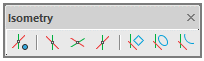
It contains:
-
The button to enable the isometric drawing mode;
-
Three buttons to set isometric planes (ISODRAFT1, ISODRAFT2 and ISODRAFT3 commands or an option on ISODRAFT command);
-
Buttons to create isorectangles, isocircles and isoarcs (rectangles, circles and arcs in an isometric projection).
Isometric drafting mode
For isometric drawing, use the Isometric drafting mode. The mode is enabled by entering the ISODRAFT command, by
 button on the Isometry toolbar or by
  button in the status bar.

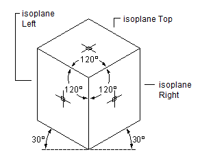
The isometry mode allows for quick switch between three isometric planes (isoplanes) by F5 key or by clicking an appropriate button on the Isometry bar.
-
 Isoplane Left. The plane allows you to create objects oriented along the axes of 90 and 150 degrees.
-
 Isoplane Right. The plane allows you to create objects oriented along axes of 30 and 90 degrees.
-
 Isoplane Top. The plane allows you to create objects oriented along the axes of 30 and 150 degrees.
Isometric Mode’s Impact on Drawing Settings
When you enable isometric drafting mode, nanoCAD automatically changes the following settings to match the selected isoplane:
-
Orthogonal direction
-
Snap orientation
-
Grid orientation
-
Polar tracking angles
-
Orientation of isometric circles, arcs, and rectangles as they are created
Creating Isometric Objects
The following commands are used to create circles, arcs, rectangles in the current isometric plane:
-
To create a circle in the current plane, use
 ISOCIRCLE command that starts the ELLIPSE command with the Isocircle option;
-
To create a rectangle in the current plane, use
 ISORECTANGLE command that starts the RECTANGLE command with the Isorectangle option;
-
To create an elliptical arc in the current isometric plane, use
 ISOARC command that starts creating an elliptical arc by the ELLIPSE with the Arc > Isoarc option.
Related System Variables
The SNAPSTYL system variable allows you to change the drawing mode. The variable values are integers.The SNAPISOPAIR system variable allows you to change the current isometric plane in the current viewport. The variable values are integers.
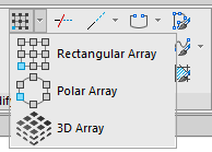
The commands now work interactively, without needing a dialog box.
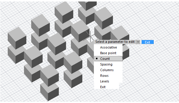
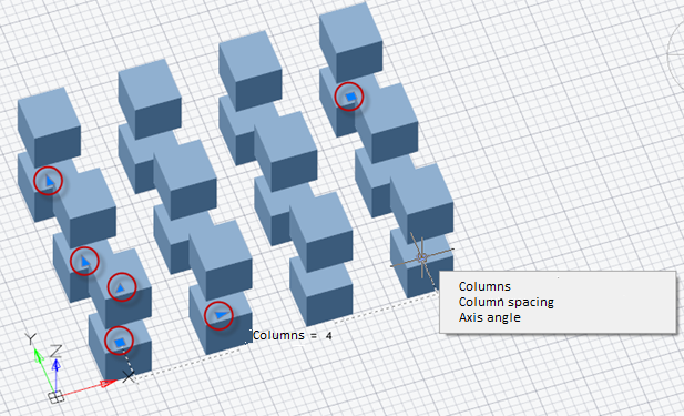
As well, nanoCAD now creates associative arrays. The objects that make up an associative array are stored as a single array object. The Array - Associativity system variable toggles arrays between associative and non-associative. Associative arrays allow you to change the number of objects and the distances between them through grips on the array or with the Properties panel.
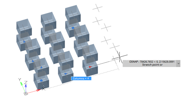
- add remove and modify block objects while maintaining the integrity of dynamic block parameters. Actions concern objects that are not involved in the block parameterization;
- convert any block to dynamic;
- replace the insertion point.
New Block Base Point Relocation
The base point of blocks can be relocated with the BBASEPT command. The base point locates the insertion point of blocks, and the position of the grip.

Reset block
Editing dynamic block inserts and then re-editing this block definition may distort the appearance of its inserts. The Reset block (RESETBLOCK) command resets the parameters of the selected dynamic block inserts to default values. It is opened from the context menu of the selected inserts or from the command line.
Now there is a possibility to transfer and save user interface configuration. To transfer settings between versions or from one computer to another, use two commands: Import UI (UIIMPORT) and Export UI (UIEXPORT).

The Export UI command allows you to save a package of individual configuration, while the Import UI command applies it to the current version of the program.
Export UI allows you to save both the composition of interface elements (ribbon, toolbars, etc.), configured in the Customize user interface dialogue box, and the display with location of interface elements (location of toolbars, palettes, command line, visual style of interface, way of the ribbon display, size and location of the program window).
Thus, you can quickly and easily transfer user configurations for convenient work with the program, as well as save the configurations package to prevent them from being lost.
If necessary, you can also edit LSP-file, which describes Import UI and Export UI, commands and edit the list of file formats included in the configuration package being exported.
Redesigned Field Dialog Box
The FIELD command’s dialog box is redesigned:
.png)
Additional format dialogue
More detailed formatting of numeric values is now available in the field editor. The Additional format button opens the dialogue box, where you can set the conversion factor, zero suppression, additional text, numeric separator.
.png)
Option for fields inside a block
Display value for block reference – the checkbox is displayed only for object properties fields that are located inside the block. For example, when editing a field inside a block attribute definition.
.png)
.png)
The parameter obliges the property to calculate its value relative to the size and orientation of the block reference in the drawing, and not relative to the internal block description space. So, for example, the coordinates of the center of the object included in the block will be calculated relative to the drawing coordinate system, and not relative to the coordinates of the block definition.
Commands to Work with Groups
Commands for working with groups now have their own place on the ribbon (Group section of the Main tab) and Group toolbar. This makes it more convenient to carry out grouping and ungrouping outside of the Object Grouping dialog box, and allows you to create unnamed groups.
.png)
.png)
.png)
|
New group (GROUP) |
A new command to create a group of objects. Unlike the New option, the GROUP command allows you to create both name and unnamed group. |
.png)
|
Exploding a group (UNGROUP) |
Exploding a group or ungrouping. |
.png)
|
Editing a group (GROUPEDIT) |
Adding or deleting objects from a group. |
.png)
|
Dialogue for creating groups (CLASSICGROUP) |
Displays the Object grouping dialogue box to manage groups. In the previous program versions this dialogue box was called by the Group command (GROUP). |
nanoCAD offers a new way to recover drawings accidently lost when exiting drawings without saving, such as when closing all open drawings at once. In other cases, objects are erased from drawings, and then the drawings are saved and closed, after which the undo/redo mechanism no longer works.
The new rescue mechanism restores them from a temporary storage, and is enabled in the Options dialogue box: Save documents section > File History.
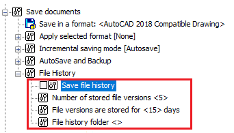
-
Save file history (FILEHISTORY variable) – determines whether the auto-save history is enabled (0 – disabled or 1 – enabled)
-
Number of stored file versions (FILEHISTORYMAX variable) – determines the maximum number of auto-saved version of each drawing file, up to 32767 versions.
-
File versions are stored for <15> days (FILEHISTORYDURATION variable) – determines the duration to store each auto-saved file, up to 32767 days (approximately 90 years).
-
File history folder – specifies the folder in which to store auto-saved files
The Open file history command (OPENHISTORY) opens files from the archive storage.
The earliest files are deleted from storage automatically once the number of archive files specified by FILEHISTORYMAX is reached. When closing nanoCAD, the storage period for files in the archive is checked, and files with a life of longer than FILEHISTORYDURATION are deleted automatically.
-
Vector maps from OpenStreetMap
-
Raster maps from ArcGis, Microsoft Bing, Google Maps, MapBox, OpenStreetMaps, OSM Topo, and Yandex Maps
-
For some providers, additions map types are supported, such as streets, satellite, hybrid, relief, and topographic
.png)
Three-dimensional terrain models can also be placed as overlays.
.png)
.png)
Improved Import and Export
- Added import and export of clouds files in E57 and ReCAP (*.rcs) formats
- Improved algorithm for importing cropped volumes
- Drag and drop nanoCAD point cloud files (*.npc) into drawings
- Set drawing measurement units in the Import dialog box
- Export point clouds in 3D PDF format
New Commands for Clipping Clouds
- Added commands for clipping cloud by sphere and cylinder shapes
- Improved clipping command interface
- New command to invert point cloud clipping boundaries
3D Geometric Snaps
The following three-dimensional snaps recognize geometry in point clouds. They are turned on and off through the Drafting Settings dialog box or at the status bar:- Point Cloud Edge Node
- Point Cloud Edge Nearest
- Point Cloud Edge Perpendicular
- Point Cloud Plane Nearest
- Point Cloud Plane Perpendicular
- Point Cloud Feature Surface
- Point Cloud Feature Axe Node
- Point Cloud Feature Axe
- Point Cloud Feature Center
.png)
.png)
The named view saved in a drawing is displayed upon opening the drawing with the new -v switch:/ncad.exe [ /drawing_file] [-list "sheet name"]
Either the - or the / character can be used for the switch./ncad.exe [ /drawing_file] [-v "view name"]
Copy OLE-link Command
The new Copy OLE-link (COPYLINK) command copies the current view to the clipboard so that it can be linked in other OLE-aware applications. An object of nanoCAD drawing type is created in the other program. This means you can insert nanoCAD drawings into Word documents as OLE objects, which can then be edited in nanoCAD by just a double-click.
.png)
Renamed OLE Commands
The names of OLE- related commands are changed to be more intuitive in the toolbar/menu interface:
In the Insert menu, the Object… item becomes OLE-Object…. (The ellipsis indicates a dialog box will be opened.)
In the Edit menu, the following items are renamed:
-
Copy view becomes Copy OLE-link
-
Links… becomes OLE-links…
-
Update all links becomes Update all OLE-links
OLE in the Properties Panel
Properties are added to the Properties panel for OLE objects.
- While holding down the Alt key, and then select any point on the locator circle
- Choosing one of the four marked points to rotate a view by 90◦.
The arrow points to the new view rotation position.
.png)
.png)
Arc Direction by Cursor Movement
nanoCAD now draws arcs (including elliptical ones) in the direction that the cursor moves. This applies to the following arc construction methods:
-
Center-Start-End
-
Start-Center-End
-
Elliptical arcs
You can also change the direction for constructing arcs by holding down the Ctrl key.
Circle by Three Tangents
Circles can now be drawn tangent to three other objects (menu Draw > Circle).
.png)
.png)
Circles Tangent to Splines and Ellipses
Now the command to create a circle by tangent, tangent and radius, allows you to specify splines, ellipses and elliptical arcs as tangents. As well, creating circles tangent to arcs or other circles is improved.
.png)
Breaking Ellipses and Closed Polylines by Two Points
When breaking an ellipse or a closed polyline with two points, the sequence of picking points determines which part of the objects to remove. (Previously, the same part always remained, regardless of the pick order.)
Lengthening in Both Directions
Lengthen (LENGTHEN) command now lengthens open objects symmetrically in both directions, through a new switch Two sides/One side. This is useful, for instance, for increasing the lengths of centerlines in both directions.
Editing Spline Fit Points with Ctrl
Spline fit points can now be edited by holding down the Ctrl key while clicking on a grip, just as with polylines. The context menu is updated to reflect this.
.png)
New Lasso Object Selection
Objects can now be selected using the lasso method: while holding down the left mouse button, move the cursor around objects. Objects are selected by a lasso or a rectangular selection frame, depending on your actions:
-
Move the cursor in the drawing area while holding down the left mouse button, the lasso outline is drawn. To end the selection, release the mouse button.
-
A single click in an empty area of the drawing starts a rectangular selection window. To complete the selection, click a second point.
The direction of cursor movement determines which objects are selected:
-
Move the cursor to the right, and objects entirely inside the area are selected. The selection area (window or lasso) is shown with a blue semi-transparent fill.
-
Move the cursor to the left, and objects inside and crossing the boundary are selected. The selection area (window or lasso) is shown with a green semi-transparent fill.
While selecting objects by the lasso method, you can cycle through three lasso modes by pressing the Space key:
-
Select only objects completely inside the lasso area
-
Select all objects inside and crossing the lasso
-
Select only objects crossing the lasso line
.png)
.png)
.png)
.png)
.png)
.png)
Selection Preview Filter
Three more objects types are added to the Selection Preview Filter dialog box: Group, Mesh, and Polyface Mesh.
.png)
Interactive Actions with the Right Mouse Button
When you drag-and-drop objects while holding down the right mouse button, a shortcut menu appears with additional actions: Move here, Copy here, Paste as block. Select one to perform the action.
.png)
Multiple Copies with Ctrl
While moving, rotating, scaling, or mirroring objects with grips, hold down the Ctrl key to create copies:
-
Select one or more objects
-
Click on a grip
-
Press the Spacebar to switch between copy, rotate, scale, or mirror actions
-
Hold down Ctrl, and then click to locate copies of the selected objects
.png)
Enhanced Rotate Command
The ROTATE command gains the Key point option. It combines the base point with the reference angle. When you specify a reference angle, the first point you pick for the angle is the base point, about which rotation takes place.
Isolation/Unisolate History
.png)
.png)
.png)
Grouping Undo/Redo
The new BEgin and End options in the Undo and Redo commands (UNDO, REDO) combine a sequence of actions to be reversed in a single step. Those commands performed after setting BEgin and before setting the End option are undone simultaneously. You can create multiple BEgin and End sets, each of which are reversed in sequence.
1. After setting the BEgin option, the Begin of command group item appears in the command list.
.png)
2. Following this, any commands you execute are added in the undo list of operations, one by one.
.png)
4. Once the End option is applied, all actions in the undo list between the beginning and the end collapse into a single group of undoable commands.
.png)
5. At this point, these commands can only be reversed together.
MATCHPROP Undo
When previously you copied properties to large numbers of objects with the MATCHPROP command, you may have accidentally copied them to a wrong object. In this case, you had to cancel the command and start copying properties anew.
To avoid this problem, a local undo option is added to the MATCHPROP command. The option appears when you specify the Select destination object(s) prompt.
.png)
.png)
Polar Spacing
The new Polar Spacing option specifies the spacing distance during polar snap, if the Polar snap (POLARDIST system variable) is turned on. When Polar Distance is set to zero, the polar spacing is equal to the Snap X spacing. Polar spacing is effective works when polar or object tracking modes are enabled.New Snap Types
-
Grid snap – sets the snap as a rectangular grid with spacing specified by Grid Spacing
- Rectangular Snap – sets rectangular as the snap style and deactivate isometric drawing mode
- Isometric Snap – sets isometric as the snap style and activates the isometric drawing mode
- Polar – sets the snap as a polar array. With polar snap and polar tracking enabled, the cursor snaps to tracking lines from the base point at angles specified on the Polar Tracking tab.
-
Turn on Grid snap
-
Set the grid to isometric snap
-
Switch to Polar snap
.png)
Polar spacing
Manages the spacing distance of the polar snap.
Spacing – polar snap spacing. Becomes available, if the Polar snap (POLARDIST system variable) is set. In case of zero value, the polar spacing is equal to the snap spacing interval by X. Works when polar or object tracking mode is enabled.Follow Dynamic UCS
The new Follow dynamic UCS setting orients the grid plane to match the XY plane of dynamic UCS automatically (GRIDDISPLAY system variable).Now you can set object snaps temporarily. To do this, enter a snap keyword during a command when you are prompted for a point, and then press Enter. The snap is set temporarily.
.png)
.png)
.png)
The full list of object snap keywords is available by typing OS_ at the command prompt, or from the status bar.
.png)
The list of object snap keywords is given by the table:
|
Keyword |
Snap type |
|
TT |
Tracking point |
|
FROM |
From |
|
M2P |
Mid between two points |
|
END |
Endpoint |
|
MID |
Middle |
|
INT |
Intersect |
|
APP |
Apparent intersection |
|
EXT |
Line extension |
|
CEN |
Center |
|
QUAD |
Quadrant |
|
TAN |
Tangent |
|
PERP |
Perpendicular |
|
PAR |
Parallel |
|
INS |
Insertion point |
|
NODE |
Node |
|
NEAR |
Nearest |
|
NONE |
Disabling object snap |
A new option Replace Z Value with Current Elevation works with for object snaps in 3D space. When enabled, it snaps to points on the XY plane in the current UCS.
The figure below shows two 3D polylines drawn object-snapped to the vertices of a mesh. The polyline in red uses the normal object snap modes; the one in blue with the Z-coordinate replacement option enabled.
.png)
.png)
In this mode, the Z coordinate value is replaced with one of the following:
-
The value of its projection to XY plane
-
The value of its projection to a plane parallel to the XY plane at the level specified by the ELEVATION variable, if it is non-zero).
Change the value of the ELEVATION variable to have the points snap at a specific distance above (positive values) or below (negative values) the XY plane.
The option is enabled in the Snap settings section of the Options dialog box, and is synchronized with the OSNAPZ variable.
.png)
.png)
.png)
Support is added for the DYNDIVIS variable when editing objects by grips;
Not all dynamic dimensions can be seen on the screen simultaneously. The number of simultaneously displayed dimensions is controlled by the DYNDIVIS variable. Depending on its value, the following can be displayed simultaneously:
-
Only one dimension (DYNDIVIS = 0)
.png)
-
Only two dimensions (= 1)
.png)
-
or all dimensions (= 2)
.png)
If only one or two dimensions are displayed simultaneously, and you need to display others, this can be done by cyclically pressing the Tab key. Press Tab until the desired dimensions are visible. On subsequent cursor movement, the selected dimensions will continue to be displayed.
.png)
.png)
.png)
Dynamic input is enhanced through the following additions:
-
Input length and angle increment fields appear when editing objects with grips
-
Dynamic input implemented for ellipse creation
-
Dynamic input fields appear for the second and the next points when drawing a variety of objects in UCS
-
Input and editing of dynamic dimensions for 3D polylines in UCS
-
DYNDIVIS variable added for editing objects with grips
-
Bugs while using dynamic input while constructing lines and circles are corrected
Using hyphen in bulleted lists
Now you can create bulleted lists using dashes.
.png)
Aligning the last line
When you add a Tab to the end of the last line of distributed multiline text, then it is aligned to the left and remains so after editing is completed.
Blocking subdimensional text
Now the cleared Dimensions box in the Main options tab of the Design Settings dialogue box (Section Edit > by double-click) also blocks editing by double-click and subdimensional multiline text.
.png)
Hiding the text background for different type objects
To hide background for multiline text, multiline attributes and multileader multiline text use a separate command .png) on the ribbon.
on the ribbon.
.png)
Objects can be selected before or after the command is performed. This allows you to apply the command to several selected different type of objects.
The command displays the Background mask dialogue box, which will display parameters for hiding background for multiline text in the first selected object.
.png)
When switching the text type of the Default value from multiline text to single-line text in the Attribute definition dialog box (ATTDEF command), a warning is now issued when the text is so long that it would be truncated. Previously, the text was completely erased.
.png)
When switching from a single-line attribute to a multiline one, the text is also preserved.
The following bugs in multileaders are corrected:
-
If a TTF font was used, then spaces were not underlined
-
Text was incorrectly underlined in multileaders with Bottom or Top attachment and Underline and Middle justification
-
Text in multileaders with Top attachment had its Left alignment changed to Right
The Modify > Multileader menu gains multileader editing commands:
.png)
For dimensions and multileaders created in other CAD systems, associativity with objects is maintained when they are imported into nanoCAD.
The associative links of dimensions with objects can be broken by shifting the grips of extension lines.
The Break dimension command (DIMBREAK) is renamed MDIMBREAK.
The Restore dimension command (DIMUNBREAK) is renamed MDIMUNBREAK.
A new version of the Break and restore dimension command (DIMBREAK) combines the functions of both commands.
Sheet lists can now be generated from sheet set as a table. From the Sheet Set toolbar, select the name of a sheet set and sheet group, then from the context menu select the Insert Sheet list item.
Templates provided for sheet sets contain the required settings. To change the style of the sheet list, edit the table style with the table style dialog box (TABLESTYLE command).
.png)
As well, you can directly select a different page setup for each sheet from the drop-down list of the Page setup option.
.png)
.png)
.png)
.png) Viewport align (ALIGNSPACE) command adjusts the pan and zoom factor of objects in layout viewports based on an alignment point in model and paper space. Points specified in model space are aligned to the points set in paper space.
Viewport align (ALIGNSPACE) command adjusts the pan and zoom factor of objects in layout viewports based on an alignment point in model and paper space. Points specified in model space are aligned to the points set in paper space.
.png)
-
Specifying a point in model space and another point in paper space offsets (pans) the view
-
Specifying two points in model space and two in paper space sets zoom scaling, panning, and rotation. The zoom factor and UCS rotation are adjusted according to the points specified.
.png)
Now when importing PDF files using the Import PDF (PDFIMPORT) command, text data are placed on the same layers, on which they were when creating a PDF file. Names of layers will start with PDF prefix. For this, in the Import PDF dialogue box, when selecting layers parameters, select the Use PDF layers option;
Solid fills in nanoCAD Platform are now imported by a fill, and not as a contour as before;
A bug with importing gradient fills from PDF, when some types of gradient fills were not imported into the drawing has been fixed. Gradient fills are imported as raster images.
.png)
.png)
You can optimize the work in the program when connecting to a workstation remotely via RDP by using the enhanced DirectX compatibility mode in the Options dialogue.
.png)
If the box is checked, DirectX 9 is used. When cleared, the default DirectX version is used. In most cases it is DirectX 11, but if it is not supported by the system, then it is DirectX 9. You can also switch DirectX version by the NCGS_TOGGLE_DIRECTX command.
nanoCAD now continues to work for another hour following the loss of your license. This allows you to complete your work. You will be reminded periodically that your license has expired.