How to Shade and Shape, or How to Create Artwork with nanoCAD
We will reproduce “The Starry Night” by Vincent van Gogh through the prism of nanoCAD (Fig. 1-2). If you look closely, you can see that various brush strokes resemble different shading types.
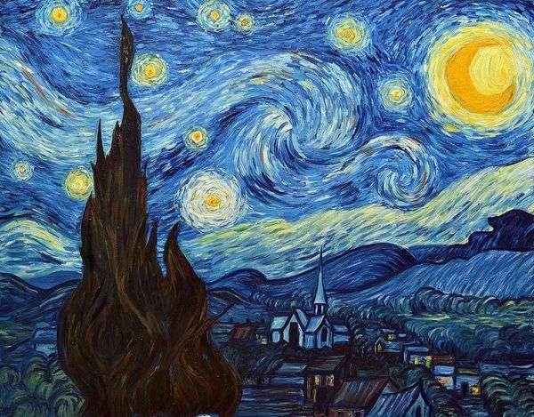
Fig. 1. Vincent van Gogh. The Starry Night
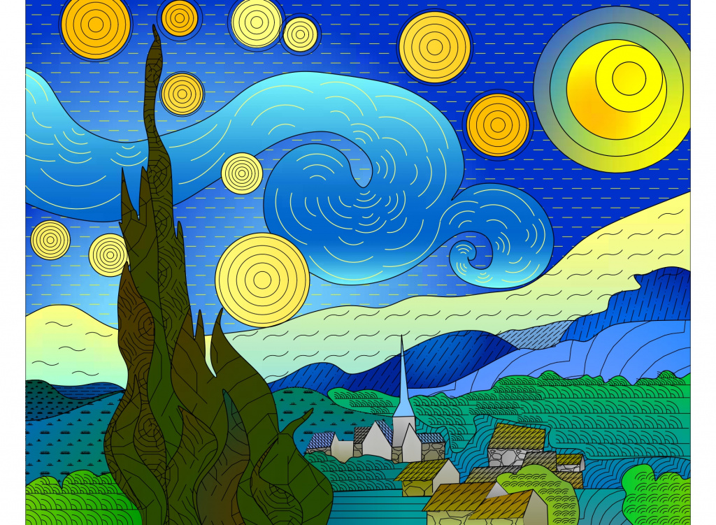
Fig. 2. "The Starry Night" through the prism of nanoCAD
Let’s not dive too deep into the correct contouring and just insert splines (the SPLINE command) and circles over the picture (the CIRCLE command). Copy it to the clipboard (Ctrl+C) and paste it into model space (Ctrl+V). You can leave the contours open if your artistic mind is telling you so. Open contours can also be shaded.
Now we have our base ready for a future masterpiece (Fig. 3)
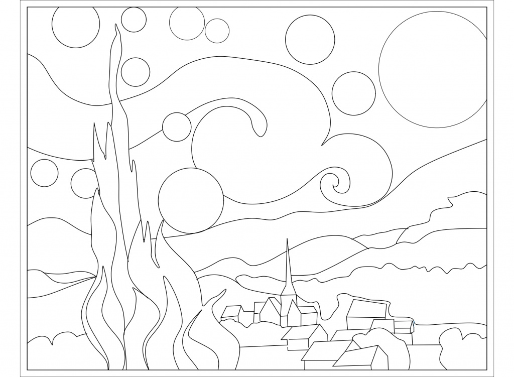
Fig. 3. The first stage: the basis of a future masterpiece
Let’s take a look at the Hatching Window. Go to the Home tab → Draw group → Hatch, or just enter the word HATCH in the command line. In the resulting dialog box, you will see that Hatch has two tabs: Hatch and Gradient.
The control panel is pretty intuitive, but let’s highlight a few features. Open the additional window by clicking on the “right” arrow in the lower right corner of the dialog box (Fig. 4).
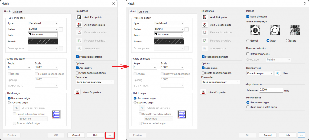
Fig. 4. Hatch dialog box
- First of all, let’s go and check what we have in the pre-installed library of standard hatch types. Select the required type from the list or call the Hatch Patterns dialog (click on the … button located to the right of the Pattern section or click on the Swatch). The entire library of shapes (*.shx) and hatch files (*.pat) is stored in the SHX folder located at the path C:\ProgramData\Nanosoft \nanoCADx6422.0\SHX. You can also add your own hatch and shape files to that folder. Restart nanoCAD after you add a new file.
- If you want to make hatching more precise, you can select a starting point (Fig. 5) and save its value by checking the Default starting point line (HPORIGIN system variable).
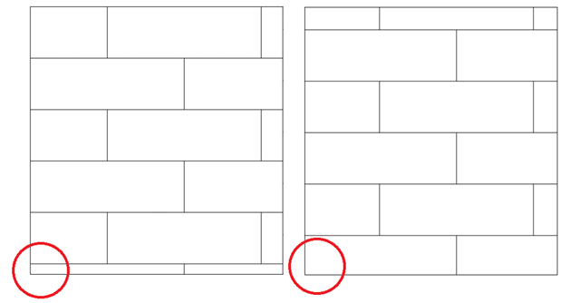
Fig. 5. Changing the hatch origin
- Use the Add button to specify a hatch/fill area: Pick points is the top button in the Boundaries block. To highlight a potential contour dynamically, check the Precalculate contours box.
- If the area is in a different plane, specify the boundaries of the hatch (Add button: Select objects).
- You can also assign associations to the hatching. When the area changes, it will adjust to the new boundaries.
- Enter a gap limit to shade unclosed areas (from 0 to 5000 in drawing units). Gaps that do not exceed this limit will be ignored and the contour will be considered closed.
It is quite easy to use the Gradient tab. The image below shows a few examples of gradient fills (Fig. 6).
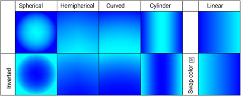
Fig. 6. Types of gradient fills
Now, we will color our picture with a gradient fill and apply shades on top of that. You can leave the "moon" without filling for now. We will prepare a custom shape for it [1]
[1] Shapes are standardized images described in an SHX file in the same way as SHX fonts.
Speed up your work ☞ if all the contours are drawn, choose FASTHATCHCMD / FASTGRADIENTCMD command to use the parameters of the previous hatch/gradient for all the contours.
Here is what we’ve got so far with color numbers indicated in parentheses: fig. 7.
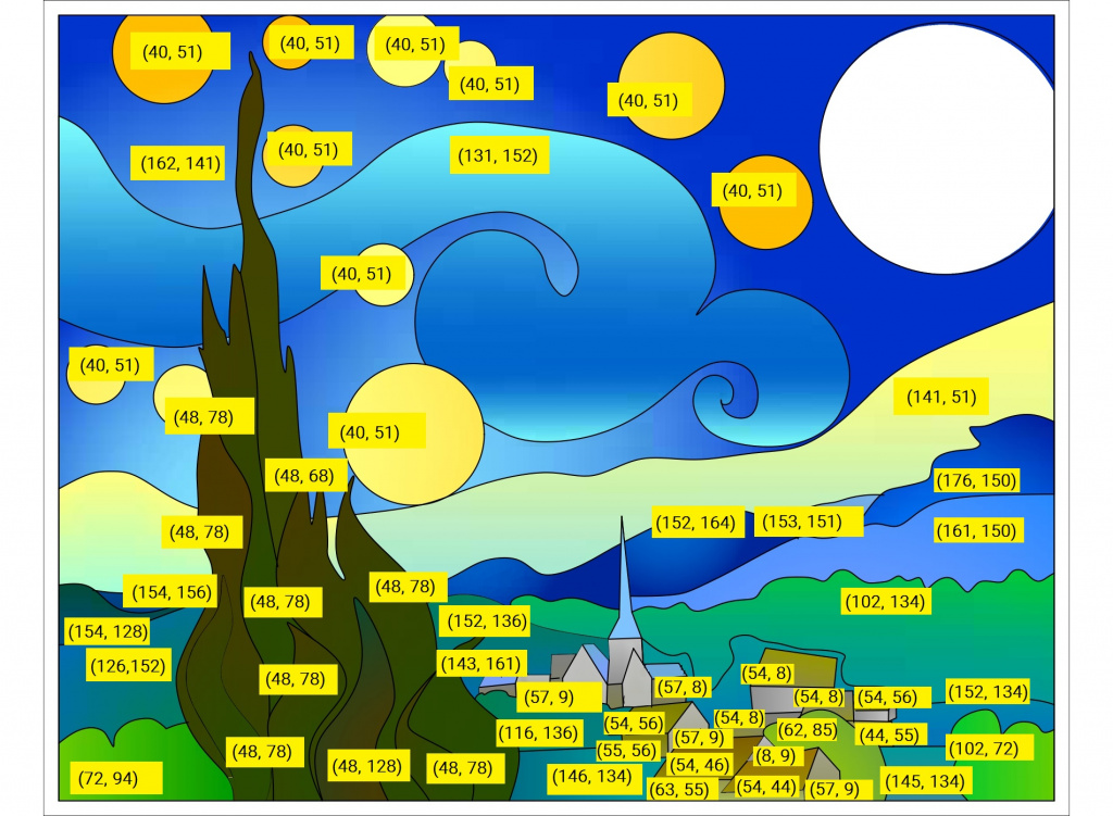
Fig. 7. Second stage: gradient fill
The hatches are stored in files with the *.pat extension, which can be viewed in any text editor. A few types of hatching can be stored in one file. Make sure that you transfer both *.dwg files with customized hatches and the hatch files. Use the eTransmit command to make your transfer successful.
In our design, hatching will cover almost the whole picture. Most of the necessary shading is available out-of-the-box in nanoCAD, but let’s create a user-defined pattern for a better understanding of the program's capabilities. Let’s take the roofs’ shading as an example.
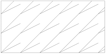
Fig. 8. Shading for House Roofs
There are two ways to create custom hatches:
1. Graphical Way:
The nanoCAD Construction module allows you to create hatches using the SPHPATTERN command through the following steps:
- Create sketch boundaries - a square with overall dimensions that do not exceed 300x300 mm. Place the bottom left corner of the square at the origin (0,0);
- Sketch a single hatch element. The sketch should be done with the help of line segments only ( LINE command), curved sections are also approximated by line segments;
- Each segment must be assigned a color;
- Create an array of the sketch within the specified area. The final sketch must be a square matrix with at least nine elements to be identified correctly. If the line in the hatch is unbroken, it must be unbroken in the final sketch. In fig. 9 the red segments were multiplied by an array (nine segments - three columns, three rows, 100 mm between columns and rows), the blue segments were multiplied by copying (five segments) and cropping/extending to the sketch boundaries.
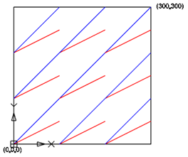
Fig. 9. The final view of the drawing for creating hatching
Each segment should not only be parallel to the segment of the same type but also lie on the same straight line with it.
Next, you need to select the hatch elements and call the SPHPATTERN command. Then, Save As and select a folder for saving (Fig. 10).

Fig. 10. Saving hatch pattern
2. In a text editor:
First, you need to specify a unique name for the hatch (starts with quotation marks "”: Unique Name of the Hatch), then add a short description, separated with commas. Enter comments to the records, separated with semicolons.
The following lines specify the location of the line segments in the hatch. They are arranged by the rule – "one line per one line segment". The segment is defined by the numbers that we enter in a certain order, separated by commas, as presented in Table 1.
Table 1. Specification of the Line Segment
|
1 |
The angle of slope of the line segment α with the X-axis of the world coordinate system (WCS) |
|
2 |
The origin where the x-axis and the y-axis intersect - The coordinates of the origin are (0,0) in WCS |
|
3 |
Offset of the line segment on the X-axis in the Segment Coordinate System (Local) |
|
4 |
Offset of the line segment on the Y-axis in the Segment Coordinate System (Local) |
|
5 |
The length of the line segment / |
|
6 |
The length of the gap with "-" sign symbol |
Let’s roll and create the "Roof" hatch using a text editor. As previously mentioned, the hatch record begins with quotation marks, followed by its name and comments.
On the next line, we will put one of the segments of the hatch. Let’s start with the red line. In order to build all the geometry quickly and accurately, we will place its origin at the point (0,0) of the world coordinate system (WCS). For illustrative purposes, we will place each identical area in a square with the length of “b” side 100 mm (Fig. 11).
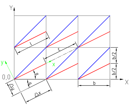
Fig. 11. Hatch Geometry
The first two columns of the table are easy to fill: the angle of inclination from the OX-axis - α (up to four decimal places), the coordinates of the line’s origin are 0.0 in the WCS. The local coordinate system (LCS) is located at the starting point of the line segment, the x-axis is a continuation of the line segment, and the y-axis is perpendicular to the line segment. Select any of the nearest lines of the same name to define the offset. Let’s say, we select a line segment to the right of the starting line. Now we are in the LCS and define the offset of the first line segment: Δx=b×cosα, Δy=b×sinα, then the length of the line - l, and the length of the gap - c to the segment of the same name, lying on the same line with the first segment.
We will do the same for the blue line. The only difference is that the blue line is constant. Therefore, we don’t need to specify the lengths of the line segment and the gap. You can see the end result in Fig. 12.

Fig. 12. Description of line segments
Let's apply our hatching to the roofs, select some of the available types and see what we’ve got (Fig. 13).
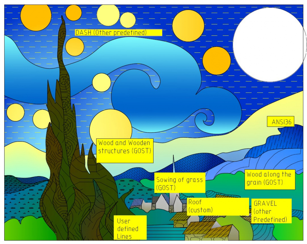
Fig. 13. Third step: applying hatch
Now you know how to create a custom hatch in two different ways. What if you can't find the correct position of the object in the hatching immediately, or some of the objects are "SOLID" filled shapes? You may have already guessed how to cope with such complexities, and have tried to manage it with only line segments. If not, you will definitely learn about it in the next article.
Next, we will add shapes to the picture. Call the Choose shape dialog box and go to the Home tab → Draw Group → SHAPE. nanoCAD has a library of shapes out-of-the-box. - these are GOST 2.303-68.shx, GOST_21_408-2013.shx and ltypeshp.shx.
Let’s also add some custom shapes (Fig. 14).
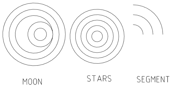
Fig. 14. Custom shapes
Similar to hatching, let’s create a file to define a shape in the *.shp format in a text editor, and then compile a file with the *.shx extension based on it. Save shapes to the C:\ProgramData\Nanosoft\nanoCAD x64 22.0\SHX folder to use shapes in the nanoCAD environment.
The shape description must contain the following:
*Shape_number, number_bytes, NAME
byte1, byte2, ..., byte N - 1, 0
Where N≤2000
The shape number is unique within one “*.shp” file. The bytes contain information about the length and direction of the shape vector.
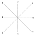
Each length and direction code is a three-character string. The first character is always 0 (it tells the program that the next two characters are interpreted as hexadecimal numbers). The second character specifies the length of the vector in drawing units. The length can be from 1 (one unit) to F (15 units). The third character specifies the direction of the vector. The correlation of code and vector direction is shown in Fig. 15.
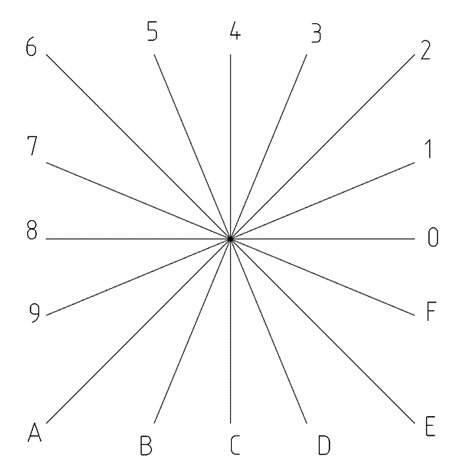
Fig. 15. Correlation of code and vector direction
Use special codes to create additional geometric shapes (circles and lines). For the purpose of this article, we will use the most common codes. However, you can always use more codes from other resources. We have also added a table of special codes here (Table 2).
Table 2. Special Сodes
|
The code |
Description |
Explanation |
|
0 |
End Shape Draw |
End shape-rendering. |
|
001 |
Pen Down (Turn On Draw Mode) |
The rendering mode is turned on when we start each shape. When the Draw Mode is on, the lines specified by vectors are drawn. |
|
002 |
Pen Up (Turn Off Draw Mode) |
When the Draw Mode is off, the pen can be moved to a new position without drawing a line. |
|
003 |
Divide Vector Lengths by Next Byte |
It is convenient to use when the vector length is not an integer (e.g. 0.5) or when the vector length exceeds the max value (F). |
|
004 |
Multiply Vector Lengths by Next Byte |
The scale factor is cumulative within a shape; that is, multiplying by 2 and again by 6 results in a scale factor of 10. You need to reverse the effect of your scale factors at the end of the shape - the program does not reset the scale factor for you. |
|
008 |
X/Y Offset , Specified by the Next Two Bytes |
Standard codes let us draw lines only in 16 fixed directions with a maximum vector length of 15 units (F). This limitation increases the efficiency of the shape building but significantly limits its capabilities. Code 8 defines the X/Y offset specified by the next two bytes. Code 8 must be followed by two bytes in the format: 008, X offset, Y offset X/Y offset values can range from -128 to + 127. You can use parentheses to improve readability. When the offset vector is drawn, the standard vectors mode is restored. |
|
009 |
Multiple Vector Offsets |
Code 9 is used to draw a sequence of nonstandard vectors. It can be specified by any number of X/Y offset pairs. The following example draws three nonstandard vectors and returns to Normal Vector mode: 009, (2.5), (7,1), (4, -5), (0,0) The code sequence is terminated by a (0,0) pair. If you don’t terminate the sequence of X/Y offset pairs with a (0,0) pair, the program will not recognize any Normal Vectors or special codes that follow. |
|
00A |
Octant Arc (defined by the next two specification bytes) |
The octant arc spans one or more 45-degree octants, starting and ending on an octant boundary. Octants are numbered counterclockwise from the 3 o'clock position, as shown in the following illustration.
The arc specification is 10, (Radius, ±0SC) The first byte (10) is the arc code. The second byte is the radius; the radius can be any value from 1 through 255. The third specification byte indicates the direction of the arc (“+” if counterclockwise, “-” if clockwise), its starting octant (s, a value from 0 through 7), and the number of octants it spans (c, a value from 0 through 7, in which 0 equals eight octants, or a full circle). You can use parentheses to improve readability. |
|
00B |
Fractional Arc (defined by the next five specification bytes) |
00B, (start offset, end offset, high radius, radius, ±0SC) The start offset and end offset represent how far from an octant boundary the arc begins or ends. The high_radius represents the most significant eight bits of the radius; the high radius will be 0 unless the radius is greater than 255 units. Multiply the high_radius value by 256 and add that value to the radius value to generate an arc radius greater than 255. The radius and ending specification byte are the same as for the octant arc specification (code 00A, described previously). The start offset is found by calculating the difference in degrees between the starting octant's boundary (a multiple of 45 degrees) and the start of the arc. Then, you multiply this difference by 256 and divide by 45. The end offset is calculated in the same way, but you use the difference in degrees between the ending octant's boundary where it intersects with the arc (a multiple of 45 degrees) and the end of the arc. If the arc starts/ends on an octant boundary, its offset is 0. For example, a fractional arc from 55 degrees to 95 degrees with a 3 unit radius would be coded as follows: 11, (56,28,0,3,012) start offset = 56 because ((55 - 45) * 256 / 45) = 56 end offset = 28 because ((95 - 90) * 256 / 45) = 28 high radius = 0 because (radius < 255) radius = 3 starting octant = 1 because arc starts in the 45 degree octant ending octant = 2 because arc ends in the 90 degree octant |
|
00С |
Arc defined by X-Y displacement and bulge |
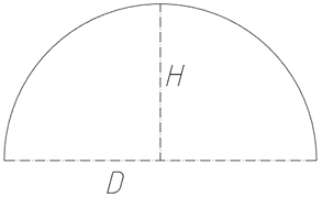
Code 00C must be followed by three bytes describing the arc: 0C, X-displacement, Y-displacement, Bulge Both the X and Y displacement and the bulge, which specifies the curvature of the arc, can range from -127 to +127.
The magnitude of the bulge is calculated as follows: k= 2D/H*127 If the arc is drawn clockwise, the sign before k is negative (“-”). . |
|
00D |
Multiple Bulge-Specified Arcs |
The polyarc code is followed triplets of parameters that specify elementary arc segments. The polyarc is terminated by a (0,0) displacement. |
It is super easy to draw your own shapes with the help of this table (Fig. 16).
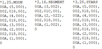
Fig. 16. Codes for "MOON", "SEGMENT", "STARS" shapes
All shapes are located in one file (Shapes3.shx). Add the shape file to the SHX folder, then you will see the ”Choose Shape” dialog window (Fig. 17).
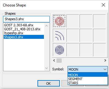
Fig. 17. Dialog box Choose Shape
Similar to hatching, when we transfer *.dwg files with unique shapes, we should also transfer the shape files. Use the eTransmit command for a successful transfer.
The whole process with shapes is similar to block building, except that you can select both the angle of rotation and the size of the shape when you insert it. Plus, it is possible to fill with a shape (Home tab → Draw Group → FillShapes), as well as with hatches, but without the Associativity option. Let’s fill a space above the horizon line with the standard WAVE shape from the GOST 2.303-68.shx file.
When the MOON shape is inserted, we can fill each circle of the moon with a different gradient (we can make it brighter to the center and darker to the edges). Check the final result of our drawing in Fig. 18.
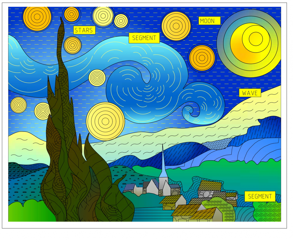
Fig. 18. Fourth step: applying shapes
Now you are ready to create your own masterpiece! In today article you learned:
-
How to use shading and gradient in nanoCAD 22;
-
What shape files are and how to use them;
-
How to fill an area with a shape;
-
Where the hatch files and shape files are stored, and how to transfer them;
-
How to create your own hatches and shapes.
You might have a question about the areas that are not filled with shades and shapes, because there should not be any "empty" areas in the final version of the painting "Starry Night through the prism of nanoCAD". At this stage, you can choose a different hatch or shape for the areas that are not filled. We used lines consisting of the "SEGMENT" shape. You will learn how to create such lines, where to store them, and how to transfer those in the next article: "Types of lines, and where they are stored".
Best of luck with your designs!
Assel Kvant,
nanoCAD technical specialist


 Es
Es  Fr
Fr  En
En 

